A method for monitoring a device for regulating the flow of a gas and a regulating system employing said method

A gas flow and gas technology, which is applied in the control/regulation system, valve operation/release device, valve device, etc., can solve the problems such as the deterioration of the performance of the pressure regulator, and achieve the effect of reducing labor costs

Active Publication Date: 2019-05-03
PIETRO FIORENTINI SPA
View PDF8 Cites 6 Cited by
  • Summary
  • Abstract
  • Description
  • Claims
  • Application Information

AI Technical Summary

Problems solved by technology

[0013] A disadvantage of the aforementioned prior art is that the criteria establish the time interval between one maintenance operation and the next based on theoretical criteria without taking into account the actual operating history of each pressure reducer
[0014] Therefore, in many practical situations, the aforementioned criteria are found to be overly cautious and can lead to maintenance work being carried out while the pressure reducer is still fully functional and thus it can still ensure safe operation for a certain period of time
[0015] On the other hand, it is also possible that unusual heavy usage of the pressure regulator requires maintenance earlier than planned
[0016] In this case, the performance of the pressure regulator can deteriorate before maintenance work can be performed, resulting in a possible risk to system safety
[0017] Similar disadvantages apply to flow control valves, which also include closures commanded in such a way as to control gas flow

Method used


Image

  • A method for monitoring a device for regulating the flow of a gas and a regulating system employing said method
  • A method for monitoring a device for regulating the flow of a gas and a regulating system employing said method
  • A method for monitoring a device for regulating the flow of a gas and a regulating system employing said method

Examples


Embodiment Construction

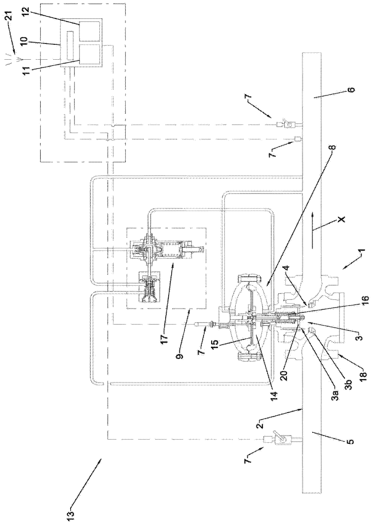
[0032] The inventive method for monitoring a device for regulating the flow of gas is described below on the basis of a regulating system in figure 1 Indicated by reference 13 in its entirety. Preferably, the above-mentioned regulating system is used in a network distributing compressed gas, in particular natural gas, in order to keep the delivery pressure of the gas to the user installation at a constant level. However, as will be apparent hereinafter, the method of the invention is equally applicable to regulating systems capable of controlling the flow of gas.

[0033] The aforementioned regulating system 13 comprises a regulating device 1 defining a flow duct 2 for conveying gas according to a predetermined direction X. Positioned in the flow duct 2 is a variable geometry closure assembly 3 which defines a restriction 4 provided with a passage area A in the flow duct 2 . In particular, the restriction 4 is delimited on two opposite sides by two corresponding sealing edge...


PUM


Abstract

A method for monitoring a device (1) for regulating the flow of a gas, comprising a flow conduit (2) and a shutter assembly (3) that defines a restriction (4) in the flow conduit (2). The method comprises the following operations: causing the transit of gas through the flow conduit (2); defining a sequence of time intervals (Z1...Zn) of corresponding durations (t1...tn); during each time interval(Zi), determining a value of density (di) and a value of velocity (Vi) of the gas at the restriction (4); calculating the product of the value of density (di), of the value of velocity (Vi), of the duration (ti) of the time interval (Zi) and of a correction coefficient (ki) to obtain a corresponding value of equivalent wear (ui); for each time interval (Zi), adding all the values of equivalent wear (u1... ui) calculated for the current time interval (Zi) and for the preceding time intervals (Z1...Z(i-1)) to obtain a cumulative value (cui); comparing the cumulative values (cui) with a predefined limit value (cu*), corresponding to a condition of maximum wear allowable for the shutter assembly (3), to obtain an indication of the condition of efficiency of the shutter assembly (3).

Description

technical field [0001] The invention relates to a method for monitoring a device regulating the flow of gas, in particular for a pressure reducer or for a flow control valve, of the type that can be used, for example, in networks for the distribution of compressed gas, in particular natural gas. [0002] The invention also relates to a regulating system employing the aforementioned method. Background technique [0003] As is known, natural gas is distributed to consumer installations through a suitable distribution network which keeps the delivery pressure to the consumer installations as constant as possible regardless of the supply pressure of the network and the flow rate provided. [0004] Delivery pressure is ensured to be maintained at a constant level by a regulating system, which may include pressure reducers positioned along the piping of the distribution network, which reduce the supply pressure of the network to the value required by the user's installations. In ...

Claims


Application Information

Patent Timeline
Patent Type & Authority Applications(China)
IPC IPC(8): F16K31/126F16K37/00G05D16/20
CPCF16K31/126F16K37/0025F16K37/0075G05D16/2095F16K37/0091
Inventor G·德菲奥
Owner PIETRO FIORENTINI SPA
Why Eureka
Try Eureka