
Metal clamp fastening structure for template secondary ridges in building construction

A technology for fastening structures and building construction, which is applied in building structures, on-site preparation of building components, and construction, etc., can solve the problems of easy instability, secondary corrugation offset, large deviation, etc., and achieves low comprehensive cost, The effect of uniform force on the steel frame and low cost

Active Publication Date: 2015-12-23
天津住总集团有限公司 +1
View PDF5 Cites 0 Cited by
  • Summary
  • Abstract
  • Description
  • Claims
  • Application Information

AI Technical Summary

Problems solved by technology

[0003] One is to control the spacing of the second flute by manual placement, and the deviation is relatively large;
[0004] Second, in the process of fastening the mold, it is easy to cause the deviation of the secondary corrugation;
[0005] The third is that the cross-section of the secondary flute is rectangular. In order to improve the mechanical performance, the short side is used to contact the formwork and the main flute. The ratio of the long and short sides is 2, which is relatively large, and it is prone to failure under the action of large concrete pouring and vibration loads. stable

Method used


Image

  • Metal clamp fastening structure for template secondary ridges in building construction
  • Metal clamp fastening structure for template secondary ridges in building construction

Examples


Embodiment Construction

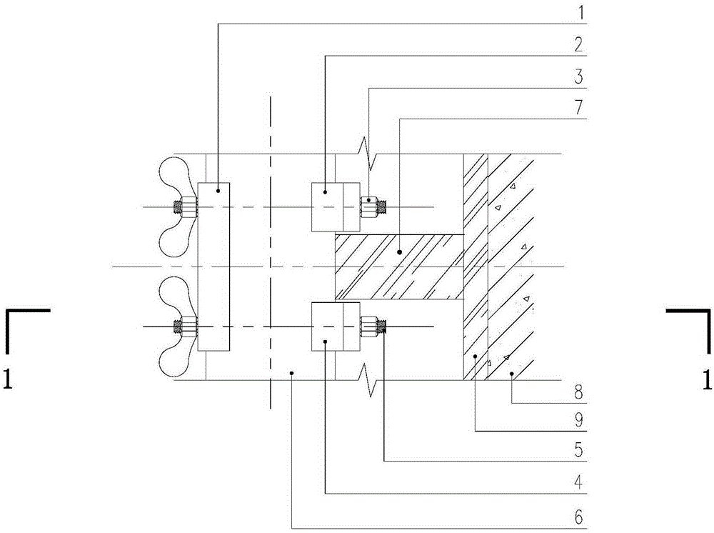
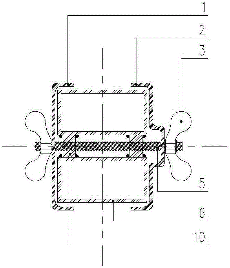
[0020] In conjunction with the accompanying drawings, the fastening structure of the formwork corrugated metal fixture in the building construction of the present invention is described.

[0021] Such as figure 1 , 2 As shown, in the building construction of the present invention, the fastening structure of the secondary flute metal fixture of the formwork is used to fix the distance between the main flute 6 and the secondary flute 7 in the mold. The main flute 6 is arranged on the outside of the secondary flute 7, and the fixture The fastening structure includes an outer U-shaped card 1 , a first inner U-shaped card 2 , a second inner U-shaped card 4 , a fixing nut 3 , and a threaded screw rod 5 . The metal fixture fastens the outer U-shaped card 1, the first inner U-shaped card 2, and the second inner U-shaped card 4 on the main flute 6 through the fixed nut 3 and the through-fastening screw 5, and the main flute 6 is made of metal. Fang Tong, Ci Leng 7 is 40×80 wooden squ...


PUM


Abstract

The invention provides a metal clamp fastening structure for template secondary ridges in building construction. Top surfaces of a first inner U-shaped clamping sheet and a second inner U-shaped clamping sheet of the clamp fastening structure are provided with U-shaped bulged ends and are respectively fixed at the two sides of each secondary ridge; an outer U-shaped clamping sheet is arranged at one side of each of two primary ridges; a first inner U-shaped clamping sheet and the second inner U-shaped clamping sheet are arranged at the other sides of the primary ridges; an all-thread screw sequentially penetrates through the outer U-shaped clamping sheet at one side of each secondary ridge, two round steel brackets and the first inner U-shaped clamping sheet, and the two ends of the all-thread screw are fastened through fixing bolts; and the all-thread screw sequentially penetrates through the outer U-shaped clamping sheet at one side of each secondary ridge, two round steel brackets and the second inner U-shaped clamping sheet, and the first inner U-shaped clamping sheet, and the two ends of the all-thread screw are fastened through fixing bolts. The metal clamp fastening structure has the effect that: the positions of the secondary ridges and distance of the secondary ridges can be precisely controlled and fixed; the stability of the secondary ridges can be greatly improved; the operation process is simple and convenient; the comprehensive cost is low; and rigidity and reliability of a mould are effectively improved, so that the quality of a concrete component is greatly improved.

Description

technical field [0001] The invention relates to a fixing device for formwork secondary corrugation in building construction, in particular to a fastening structure of formwork secondary corrugation metal fixtures in building construction. Background technique [0002] In general building construction, the reinforced concrete components cast on site include columns, beams, slabs, etc., and molds need to be set. The mold is generally composed of multi-layer wood plywood, generally called formwork, the secondary flute is 40×80 wooden square, or metal square pass, the main flute is double 40×80 metal square pass, and pull bolts. In order to ensure the overall rigidity of the mold, the spacing of the secondary corrugations cannot be greater than the spacing required by the calculation. However, there are three shortcomings in the construction, resulting in poor quality of poured concrete components, and quality defects such as surface ripples and protrusions are prone to occur. ...

Claims


Application Information

Patent Timeline
Patent Type & Authority Applications(China)
IPC IPC(8): E04G17/065
Inventor 张涛张振辉沈勤许丽华熊延军娄四林安建平于雪霞赵长宝葛贤启程洋毕江寰
Owner 天津住总集团有限公司
Learn More