Eureka AIR delivers breakthrough ideas for toughest innovation challenges, trusted by R&D personnel around the world.

Traction type ocean environment automatic monitoring system driven by wave energy

A marine environment and automatic monitoring technology, applied in ocean energy power generation, signal transmission systems, motor vehicles, etc., can solve problems such as difficult energy supply, increased equipment cost, and unguaranteed continuity, so as to save manpower and realize real-time monitoring Effect

Inactive Publication Date: 2012-03-21
JIMEI UNIV +1
View PDF4 Cites 19 Cited by
  • Summary
  • Abstract
  • Description
  • Claims
  • Application Information

AI Technical Summary

Problems solved by technology

The method of measuring by ship-borne instruments requires the ship to cooperate with the winch to complete the monitoring of marine environmental parameters multiple times. If long-term continuous observation is required, a lot of manpower and financial resources are required; traditional submerged buoy measurement is generally powered by batteries, but due to long-term Unattended, energy supply is a big problem
It is necessary to manually retract the submersible and replenish the power supply at intervals, and the continuity of the measurement cannot be guaranteed
Moreover, the submerged mark measurement method needs to lay multiple sensors in layers, which greatly increases the equipment cost.
These two types of traditional measurement methods are no longer able to meet the needs of increasingly large monitoring tasks of marine environmental parameters.

Method used


Image

  • Traction type ocean environment automatic monitoring system driven by wave energy
  • Traction type ocean environment automatic monitoring system driven by wave energy
  • Traction type ocean environment automatic monitoring system driven by wave energy

Examples


Embodiment Construction

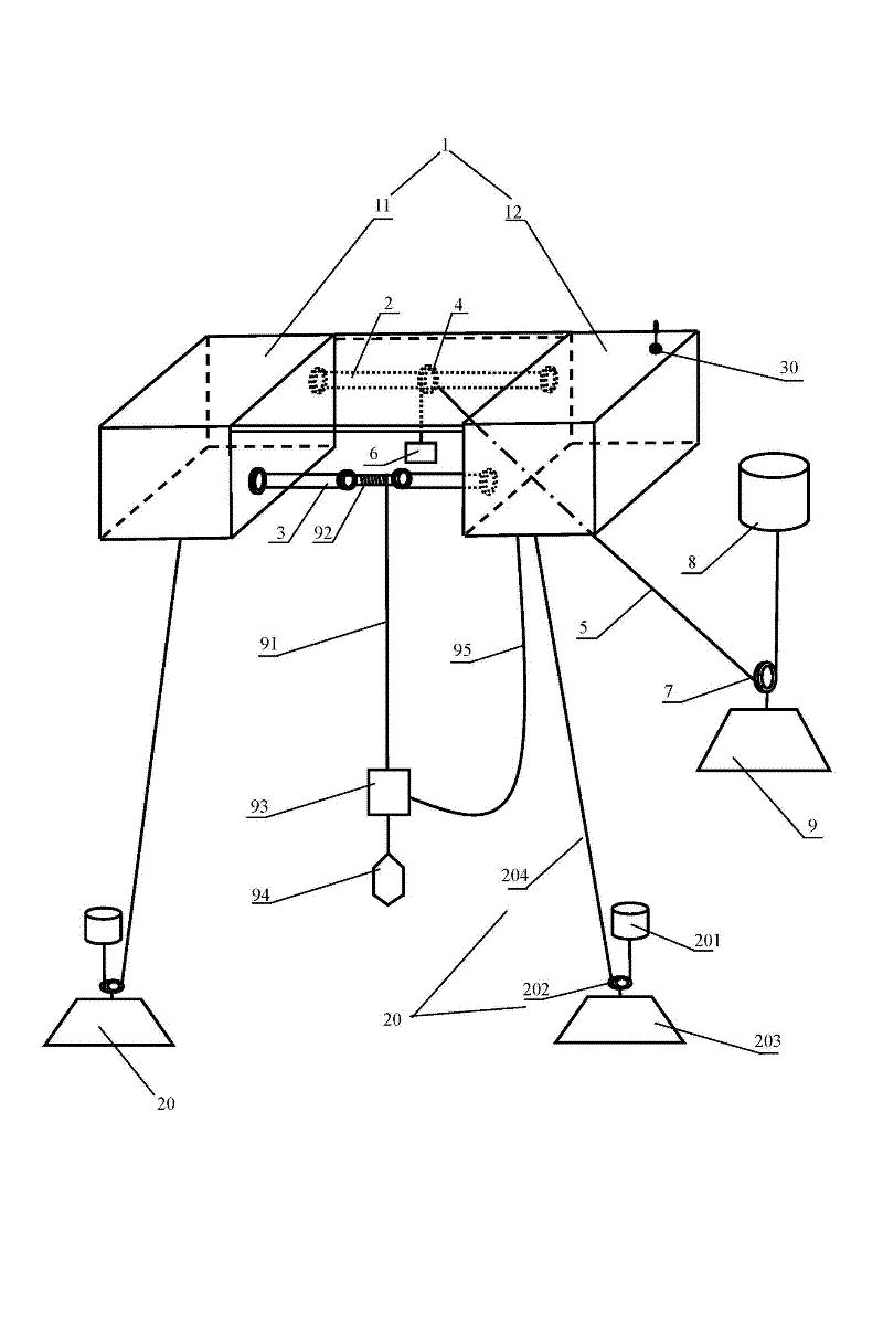
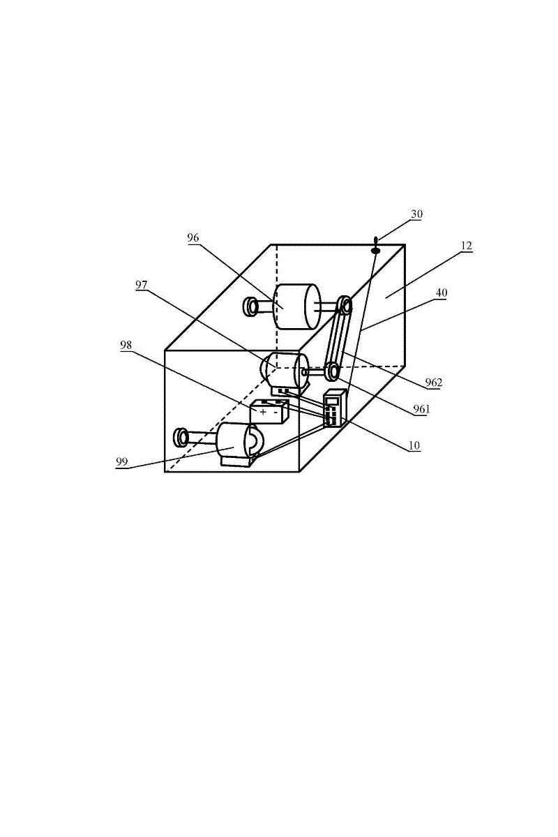
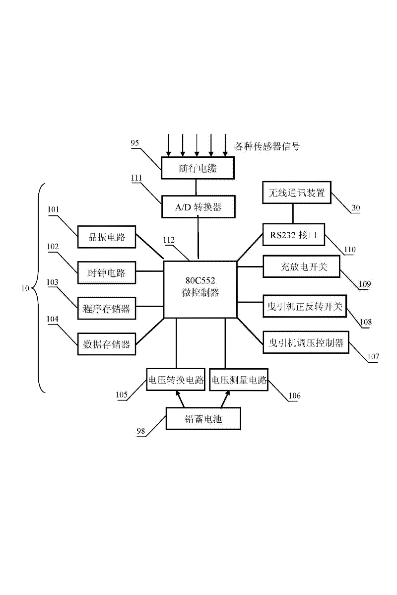
[0019] Such as figure 1 , figure 2 As shown, the present invention is a traction type marine environment automatic monitoring system driven by wave energy, which includes a sea surface nacelle 1, a generator rotating shaft 2, a traction machine rotating shaft 3, an overrunning clutch 4, a transmission cable 5, and a counterweight body 6. Fixed pulley 7, oscillating float 8, heavy anchor block 9, chain 91, sprocket 92, measuring platform 93, tension hammer 94, accompanying cable 95, speed increasing gear box 96, permanent magnet generator 97, lead storage battery 98. DC traction machine 99, automatic control device 10, anchoring device 20, and wireless communication device 30.

[0020] The sea surface engine room 1 is composed of a left side sea surface engine room 11 and a right side sea surface engine room 12 which are arranged oppositely. The left sea surface engine room 11 and the right sea surface engine room 12 have the same weight and are kept horizontal on the sea surface...


PUM


Abstract

The invention discloses a traction type ocean environment automatic monitoring system driven by wave energy, which is composed of a sea surface cabin, an oscillation float, a measuring platform, a permanent magnet generator, a direct current tractor, a lead storage battery, an automatic control device, a wireless communication device and the like. The wave energy is converted into electric energyby utilizing the relative motion of the sea surface cabin and the oscillation float. Charging and discharging of the lead storage battery are completed under control of the automatic control device. The automatic control device gives orders to drive the direct current tractor to rotate positively or negatively so as to drive the measuring platform to float upwards and dive downwards circularly. The measuring platform can continuously measure ocean environment parameters during a moving process, and the wireless communication device is utilized for automatically uploading the measured data to a monitoring center on the bank. The traction type ocean environment automatic monitoring system can achieve self energy supplement, accurate control of speed and location of the measuring platform and uploading of the measured data of ocean environment parameters in real time, and has great advantages compared with a traditional ocean environment monitoring device.

Description

Technical field [0001] The invention relates to the technical field of marine environment monitoring, in particular to a traction type marine environment automatic monitoring system driven by wave energy and capable of measuring marine environmental parameters in offshore areas. Background technique [0002] Long-term, continuous, and real-time monitoring of marine environmental parameters plays an important role in human activities such as oceanographic research, marine engineering construction, and maritime defense and security. In the past, there are generally two methods for measuring marine environmental parameters. One is to measure by a shipboard instrument; the other is to use a submarine target layered sensor group to measure. The method of measuring by the shipboard instrument requires the ship to cooperate with the winch to complete the monitoring of the marine environmental parameters many times. For long-term continuous observation, it takes a lot of manpower and fin...

Claims


Application Information

Patent Timeline
Patent Type & Authority Applications(China)
IPC IPC(8): F03B13/18H02J7/32G08C17/02B63B35/00
CPCY02E10/38Y02E10/30
Inventor 杨绍辉何宏舟
Owner JIMEI UNIV
Why Eureka
Eureka Blog
Learn More