
A liftable and rotatable anti-drop sound box

A sound and anti-drop technology, applied in the direction of frequency/direction characteristic devices, etc., can solve the problems of affecting the use effect of the sound, unable to adjust the position, etc., and achieve the effect of protecting from damage

Inactive Publication Date: 2019-05-03
GUANGZHOU AUDINGNUO TECH CO LTD
View PDF3 Cites 2 Cited by
  • Summary
  • Abstract
  • Description
  • Claims
  • Application Information

AI Technical Summary

Problems solved by technology

[0004] Most of the existing audio and sound effects are controlled by internal electronic technology, but the location of the audio installed in the room is different, the refraction and reflection of the sound are also different, and the sound effect will change accordingly. Most of the installation positions are fixed and cannot be adjusted, which will affect the use of the sound

Method used


Image

  • A liftable and rotatable anti-drop sound box
  • A liftable and rotatable anti-drop sound box
  • A liftable and rotatable anti-drop sound box

Examples


Embodiment 1

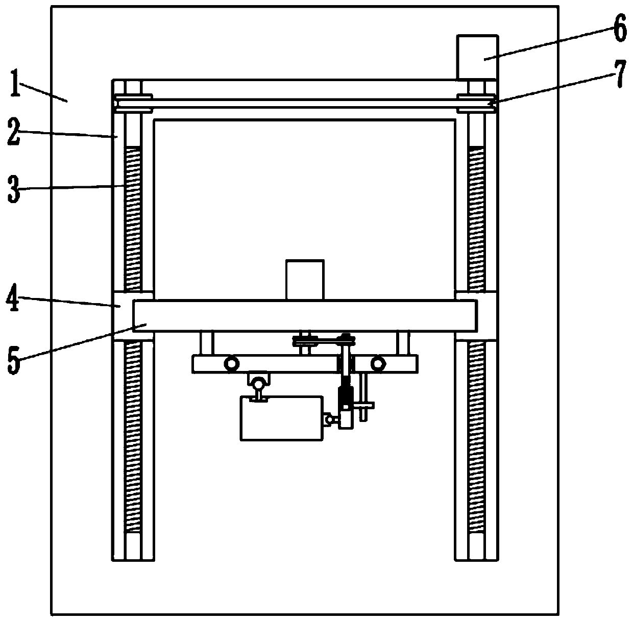
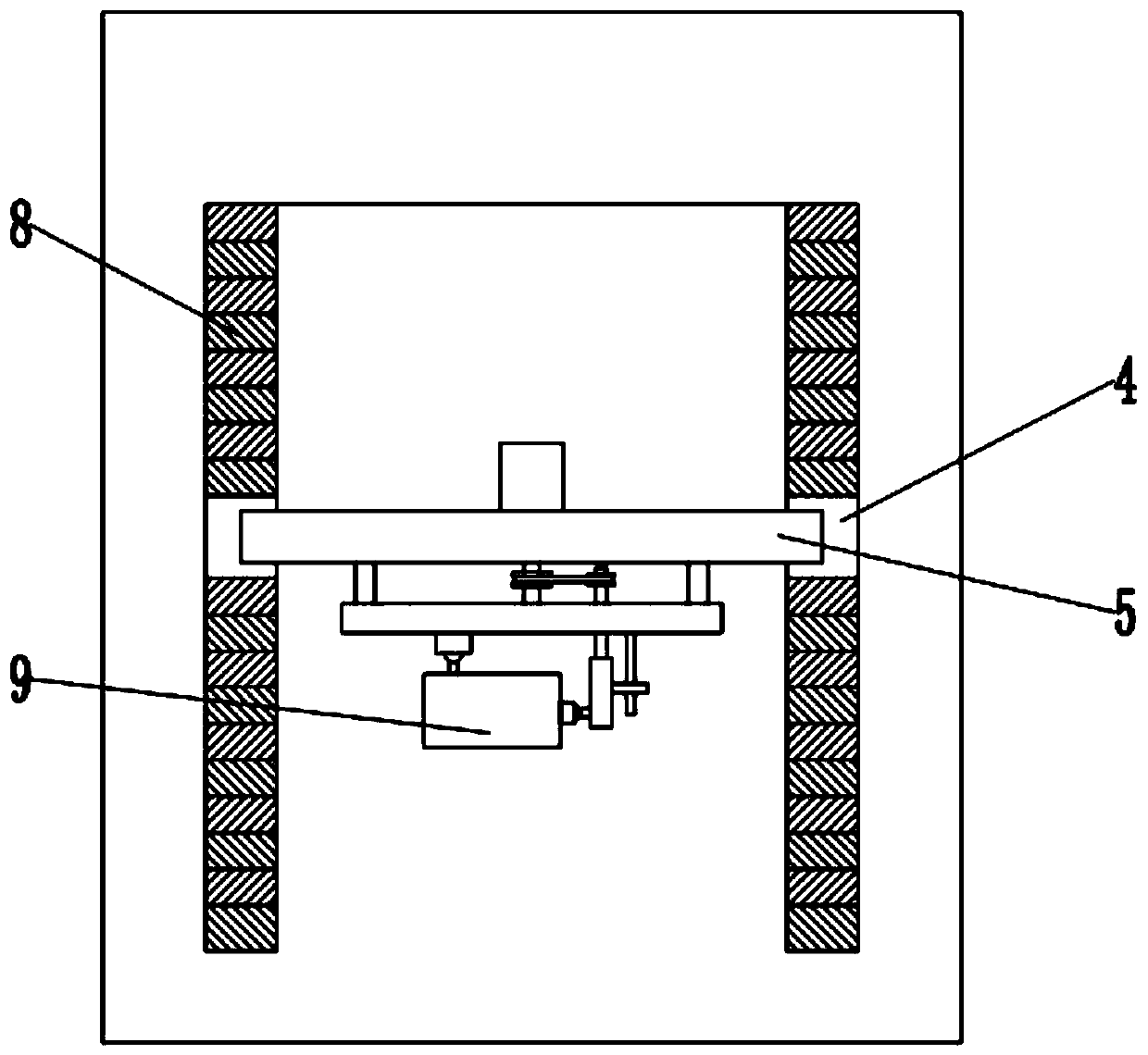
[0022] see Figure 1~3 , in an embodiment of the present invention, a liftable and rotatable anti-fall audio system includes a mounting backboard 1 and a lifting seat 5; the mounting backboard 1 is fixedly mounted on a wall, and a U The left and right sides of U-shaped groove 2 and U-shaped groove 2 are symmetrically rotated and installed with two first screw rods 3, and the upper ends of the two first screw rods 3 are connected through the transmission of the first belt 7, so that the two first screw rods 3 rotate in the same direction at the same time , the inside of the installation backplane 1 is also fixedly installed with a first motor 6, the output end of the first motor 6 is fixedly connected with one of the first screw rods 3; the first screw rod 3 is also threaded with a screw sleeve 4, and the two Each screw sleeve 4 is all slidably connected with the U-shaped groove 2, and the left and right sides of the lifting seat 5 are respectively fixedly connected with two sc...

Embodiment 2

[0026] see Figure 1~4 , in an embodiment of the present invention, a liftable and rotatable anti-fall audio system includes a mounting backboard 1 and a lifting seat 5; the mounting backboard 1 is fixedly mounted on a wall, and a U The left and right sides of U-shaped groove 2 and U-shaped groove 2 are symmetrically rotated and installed with two first screw rods 3, and the upper ends of the two first screw rods 3 are connected through the transmission of the first belt 7, so that the two first screw rods 3 rotate in the same direction at the same time , the inside of the installation backplane 1 is also fixedly installed with a first motor 6, the output end of the first motor 6 is fixedly connected with one of the first screw rods 3; the first screw rod 3 is also threaded with a screw sleeve 4, and the two Each screw sleeve 4 is all slidably connected with the U-shaped groove 2, and the left and right sides of the lifting seat 5 are respectively fixedly connected with two sc...


PUM


Abstract

The invention discloses a liftable and rotatable anti-drop sound box. The sound box comprises a mounting back plate and a lifting seat; the mounting back plate is fixedly mounted on a wall surface, aU-shaped groove is formed in the front surface of the mounting back plate, and two first screw rods are symmetrically and rotationally mounted on the left side and the right side of the U-shaped groove; The first screw rod is further in threaded connection with screw sleeves, the two screw sleeves are in sliding connection with the U-shaped groove, and the left side and the right side of the lifting base are fixedly connected with the two screw sleeves correspondingly; A mounting plate is arranged on the lower side of the lifting base, the left side and the right side of the mounting plate arefixedly connected with the lifting base through supports, and a rotating disc is rotationally mounted in the mounting plate. A sound installation base is further arranged on the lower side of the rotating disc, the sound installation base is of a hollow box structure, and a sound is arranged in the sound installation base. The loudspeaker box can be driven to move up and down, the loudspeaker boxcan be driven to rotate, meanwhile, vibration force is absorbed and converted when the loudspeaker box mounting base falls off accidentally, and the loudspeaker box is protected from being damaged.

Description

technical field [0001] The invention relates to the field of audio technology, in particular to a liftable and rotatable anti-drop audio system. Background technique [0002] Sound refers to sounds other than human language and music, including sounds from the natural environment, animals, machines and tools, and various sounds from human actions. [0003] Audio probably includes power amplifiers, peripheral equipment (including compressors, effects, equalizers, VCD, DVD, etc.), speakers (speakers, speakers), mixers, microphones, display devices, etc. add up to a set. Among them, speakers are sound output devices, speakers, subwoofers and so on. A speaker includes high, low, and medium speakers, three but not necessarily three. The development history of technology can be divided into four stages: tube, transistor, integrated circuit, and field effect tube. [0004] Most of the existing audio and sound effects are controlled by internal electronic technology, but the loca...

Claims


Application Information

Patent Timeline
IPC IPC(8): H04R1/20
Inventor 赵建磊
Owner GUANGZHOU AUDINGNUO TECH CO LTD
Learn More