
Through-flow fan blade lifting detection device and method

A cross-flow fan blade and re-testing technology, applied in measuring devices, using stable tension/pressure testing material strength, instruments, etc., can solve the problems of high labor intensity of employees, deformation and cracking, and the lack of universality of test data.

Pending Publication Date: 2019-05-03
GREE ELECTRIC APPLIANCES CHONGQING +1
View PDF0 Cites 0 Cited by
  • Summary
  • Abstract
  • Description
  • Claims
  • Application Information

AI Technical Summary

Problems solved by technology

[0008] The detection bracket is too simple, and there is a potential safety hazard of deformation and cracking of the bracket under the action of the overweight hanging box;
[0009] Since the fixed base of the cross-flow fan blade cannot be adjusted, the accuracy of the hoisting position is not high, and there are large errors in the data of the hoisting test, which is not reliable;
[0010] During the testing process, the tester needs to add heavy objects. Since the break time of the fan blade is not fixed, it is very likely that the cross-flow fan blade will break when adding heavy objects, and the tester's feet will be injured, which poses a great safety hazard;
[0011] After the test is completed, the tester needs to remove the 35kg weight from the wind blade, which requires high labor intensity for the staff and has the disadvantage of wasting physical strength;
[0012] During the detection process, the hanging box is released manually, and the time and strength of each release are random, which will affect the test results;
[0013] The detection bracket has poor stability and low safety factor. It can only detect the strength of the fan blade qualitatively, but cannot quantitatively judge the quality of the fan blade.
[0014] It can be seen that the efficiency of the existing cross-flow fan blade lifting test is low, the test timing is not accurate, the test data is not universal, and the detection test cannot be carried out on other types of fan blades; and the safety of the detection process is low, and the labor intensity of employees is high. high

Method used


Image

  • Through-flow fan blade lifting detection device and method
  • Through-flow fan blade lifting detection device and method
  • Through-flow fan blade lifting detection device and method

Examples


Embodiment Construction

[0058] In order to make the purpose, technical solution and advantages of the present invention clearer, the technical solution of the present invention will be described in detail below. Apparently, the described embodiments are only some of the embodiments of the present invention, but not all of them. Based on the embodiments of the present invention, all other implementations obtained by persons of ordinary skill in the art without making creative efforts fall within the protection scope of the present invention.

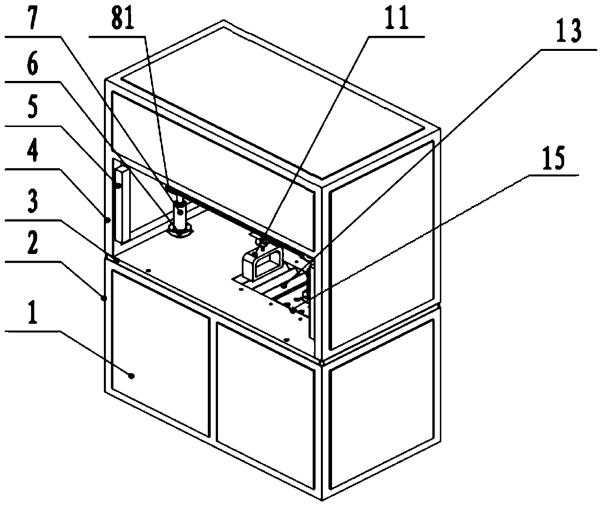
[0059] figure 1 It is a schematic diagram of the overall structure provided by Embodiment 1 of the device for detecting the hanging weight of cross-flow blades of the present invention.

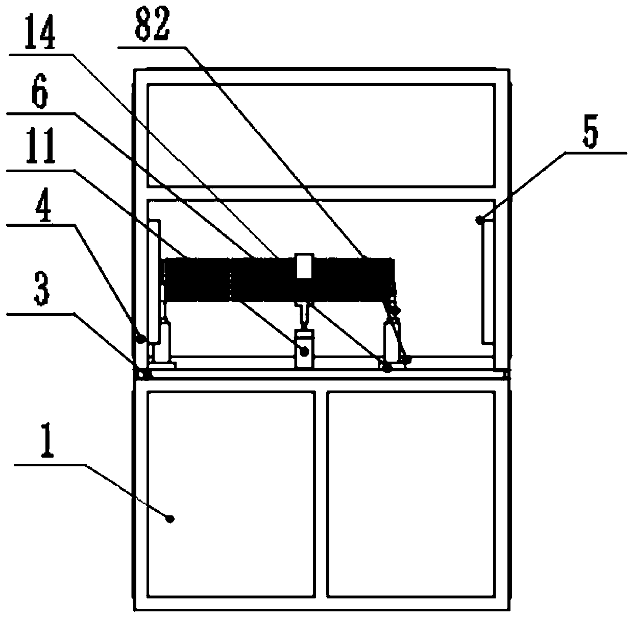
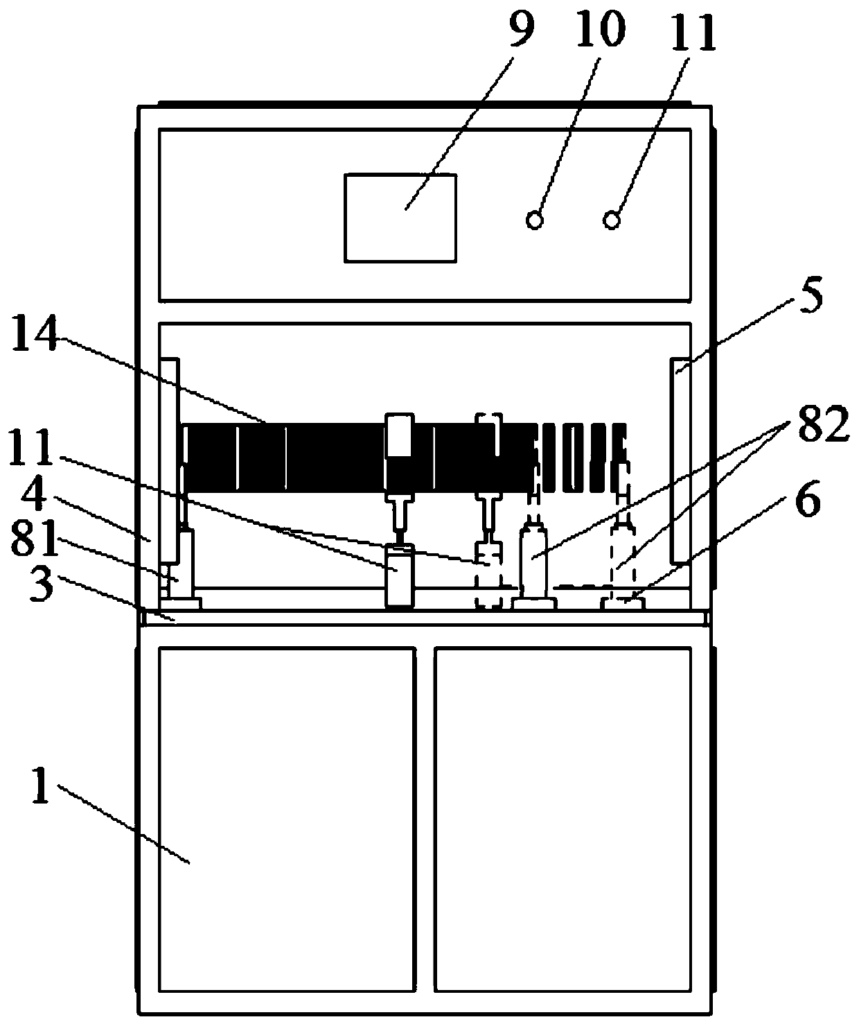
[0060] Such as figure 1 and figure 2 As shown, the detection device described in this embodiment includes:

[0061] work surface 3;

[0062] A group of brackets installed on the work surface 3;

[0063]The set of brackets includes a first bracket 81 and a second bracket ...


PUM


Abstract

The invention relates to a through-flow fan blade lifting detection device and method. The detection device comprises a work table top and at least one group of supports mounted on the work table top;each group of supports includes first and second supports; electric cylinders are arranged in the first and second supports respectively, and after operation of the electric cylinders, the first andsecond supports are driven to rise or fall; a lifted weight and a controller are also included, the lifted weight is hung on a through-flow fan blade via a connecting piece, and can rise or fall withthe through-flow fan blade; and the controller is electrically connected with the electric cylinders, and used to control operation of the electric cylinders. The detection device can drive the through-flow fan blade to rise / fall automatically via the supports and electric cylinders on the work table top, and thus, lifting detection of the through-flow fan blade is realized; a detection result ishighly stable, a detection process is safe and the labor intensity is low; and the detection device can be provided with multiple groups of supports, so that lifting detection can be carried out on multiple through-flow fan blades simultaneously, and the detection efficiency is high.

Description

technical field [0001] The invention relates to the technical field of equipment detection, in particular to a device and method for detecting the lifting weight of cross-flow fan blades. Background technique [0002] The cross-flow fan blade is welded one by one by a single-section small blade through a cross-flow fan blade welding machine, and the spot welding strength is not enough during the welding process. In the prior art, a lifting test can be carried out at the middle position of the cross-flow fan blade to detect the strength of the cross-flow fan blade. When cross-flow fan blades enter the factory for inspection, a fracture test is required, and the fracture test is carried out with a lifting device. The detection steps are as follows: [0003] 1. Install the cross-flow fan blade to be tested on the left and right fixed tooling frames to keep the cross-flow fan blade in a horizontal state; [0004] 2. Hang the suspension ring at the middle of the wind wheel at t...

Claims


Application Information

Patent Timeline
IPC IPC(8): G01N3/08G01N3/02
Inventor 杜祥卫张浩田润龙智明
Owner GREE ELECTRIC APPLIANCES CHONGQING
Learn More