
Dual-stress concentration structure micro pressure sensor core body and manufacturing method thereof

A micro-pressure sensor and stress concentration technology, which is applied in the measurement of the property force of piezoelectric resistance materials, etc., can solve the problem of unsolved sensitivity and linearity, sensitivity and frequency response characteristics, secondary stress concentration effect is general, influence Effective control of linearity and other issues to achieve mass production, improve dynamic response characteristics, and facilitate processing

Inactive Publication Date: 2019-05-03
SUZHOU CHANGFENG AVIATION ELECTRONICS
View PDF14 Cites 11 Cited by
  • Summary
  • Abstract
  • Description
  • Claims
  • Application Information

AI Technical Summary

Problems solved by technology

[0007] However, the above-mentioned prior art still cannot achieve a very satisfactory effect in terms of linearity. In terms of design stress design of compressive and tensile stress at the varistor, due to the limitation of the structure of the embossed beam itself, the effect of secondary stress concentration is general. This directly limits the improvement of sensitivity
Moreover, there is no direct restriction on the central strain of the diaphragm, and the sensitivity and the restriction structure work independently, which directly affects the effective control of linearity, and the inherent contradiction between sensitivity and linearity, sensitivity and frequency response characteristics has not been resolved.

Method used


Image

  • Dual-stress concentration structure micro pressure sensor core body and manufacturing method thereof
  • Dual-stress concentration structure micro pressure sensor core body and manufacturing method thereof
  • Dual-stress concentration structure micro pressure sensor core body and manufacturing method thereof

Examples


Embodiment Construction

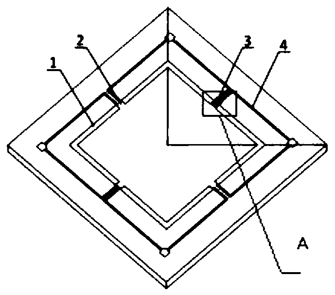
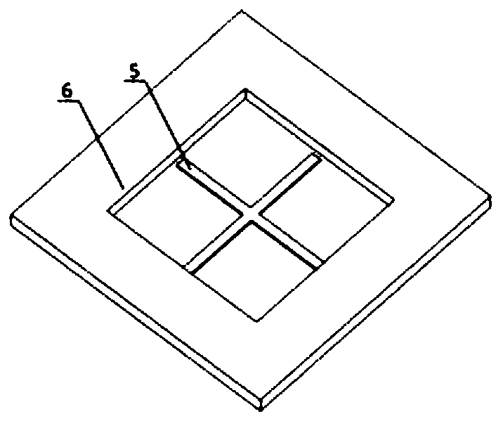
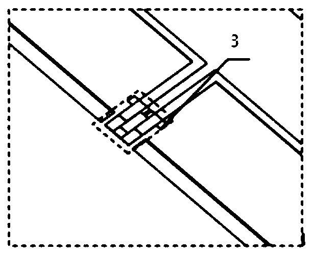
[0044] A core body of a micro-pressure sensor with a double stress concentration structure includes a substrate 6, and the core body uses N-type 100 crystal orientation SOI as the material of the substrate 6. And the diaphragm provided in the middle of the base 6, the upper surface of the diaphragm is evenly provided with more than two discontinuous grooves 1 in the circumferential direction, ribs 2 are formed between the ends of adjacent grooves 1, and the ribs 2 are arranged symmetrically on the upper surface of the diaphragm. A piezoresistor strip 3 is arranged at the stress concentration place of the rib 2, and the piezoresistor strip 3 is connected to form a Wheatstone bridge through metal leads. A protruding rigid structure 5 is formed on the lower surface of the diaphragm, and the center of the rigid structure 5 passes through the center of the back of the core to reduce the displacement of the diaphragm center; the outer end surface of the rigid structure 5 is in conta...


PUM

PropertyMeasurementUnit
thicknessaaaaaaaaaa
thicknessaaaaaaaaaa
thicknessaaaaaaaaaa

Abstract

The invention provides a dual-stress concentration structure micro pressure sensor core body and a manufacturing method thereof. The core body includes a substrate and a diaphragm arranged at the middle of the substrate, wherein an upper surface of the diaphragm is circumferentially uniformly provided with more than two discontinuous grooves, a ribbed plate is formed between end portions of the adjacent grooves, the ribbed plate is symmetrically arranged on the upper surface of the diaphragm, a stress concentration portion of the ribbed plate is provided with a pressure-sensitive resistor bar,the pressure-sensitive resistor bar is connected through a metal leading wire to form a Wheatstone bridge, a lower surface of the diaphragm is formed with a convex rigid structure, the center of therigid structure passes through the center portion of a back surface of the core body to reduce displacement of the diaphragm center, an outer end surface of the rigid structure is superposed with inner rims of the grooves and is not connected with the substrate, so dual-stress concentration is formed at the position of the pressure-sensitive resistor bar when the pressing force acts on the diaphragm, and thereby reliable and accurate measurement of a micro pressure sensor is guaranteed.

Description

technical field [0001] The invention relates to the technical field of MEMS silicon piezoresistive micro-pressure sensors, in particular to a double stress concentration micro-pressure sensor core and a preparation method. Background technique [0002] In recent years, MEMS micro-pressure sensors have been widely used in wind tunnel testing, aircraft altitude detection and biomedicine due to their advantages of small size, light weight, high sensitivity and natural frequency. For example, in the process of monitoring the altitude of the aircraft, the pressure and the altitude have a linear relationship, and the altitude of the aircraft can be reflected by measuring the pressure of the environment where the aircraft is located. During this process, the atmospheric pressure will change from hundreds of kilopascals (kPa) to several kilopascals (Pa), which requires the sensor to have high sensitivity to reflect small pressure changes, and then provide accurate altitude changes. ...

Claims


Application Information

Patent Timeline
Patent Type & Authority Applications(China)
IPC IPC(8): G01L1/18
Inventor 李闯王尊敬张磊王天资
Owner SUZHOU CHANGFENG AVIATION ELECTRONICS
Learn More