
Assembly type television splicing screen mounting device and mounting method thereof

A technology for installing devices and splicing screens, which is applied in the direction of supporting machines, mechanical equipment, machine tables/brackets, etc., can solve the problems of not being easy to fix equipment, difficult to correct, and inconvenient installation, so as to achieve convenient installation and adjustment of splicing screens, Easy disassembly and assembly, stable and reliable connection

Active Publication Date: 2019-05-03
GUANGZHOU MECHANICAL & ELECTRICAL INSTALLATION +2
View PDF24 Cites 3 Cited by
  • Summary
  • Abstract
  • Description
  • Claims
  • Application Information

AI Technical Summary

Problems solved by technology

[0002] The current TV wall is a super-large-screen TV wall composed of multiple screen units, while the conventional TV wall bracket is made by welding alloys on site, or connected by self-tapping screws on the alloy brackets. It is difficult to adjust the achievements, and it is not easy to fix the equipment during the production process. It is difficult to correct the deviation of the bracket. When installing the screen on the top of the TV wall, the staff needs to install the splicing screen units one by one at a high place. The installation is inconvenient and time-consuming. high risk factor

Method used


Image

  • Assembly type television splicing screen mounting device and mounting method thereof
  • Assembly type television splicing screen mounting device and mounting method thereof
  • Assembly type television splicing screen mounting device and mounting method thereof

Examples


Embodiment Construction

[0030] The following will clearly and completely describe the technical solutions in the embodiments of the present invention with reference to the accompanying drawings in the embodiments of the present invention. Obviously, the described embodiments are only some, not all, embodiments of the present invention. Based on the embodiments of the present invention, all other embodiments obtained by persons of ordinary skill in the art without creative efforts fall within the protection scope of the present invention.

[0031]In the description of the present invention, it should be noted that the terms "center", "longitudinal", "transverse", "upper", "lower", "front", "rear", "left", "right", " The orientations or positional relationships indicated by "vertical", "horizontal", "top", "bottom", "inner", "outer", etc. are based on the orientation or positional relationships shown in the drawings, and are only for the convenience of describing the present invention and simplifying D...


PUM


Abstract

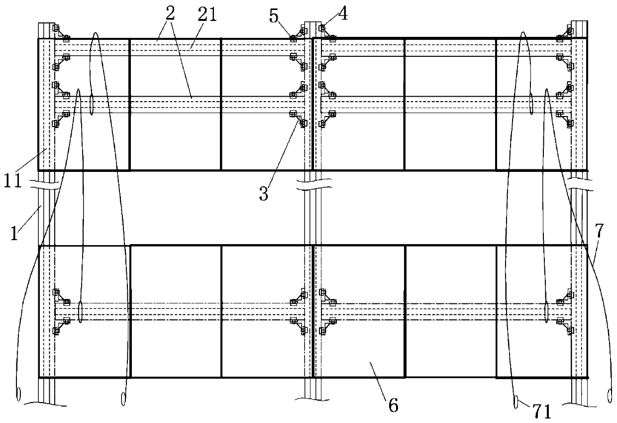
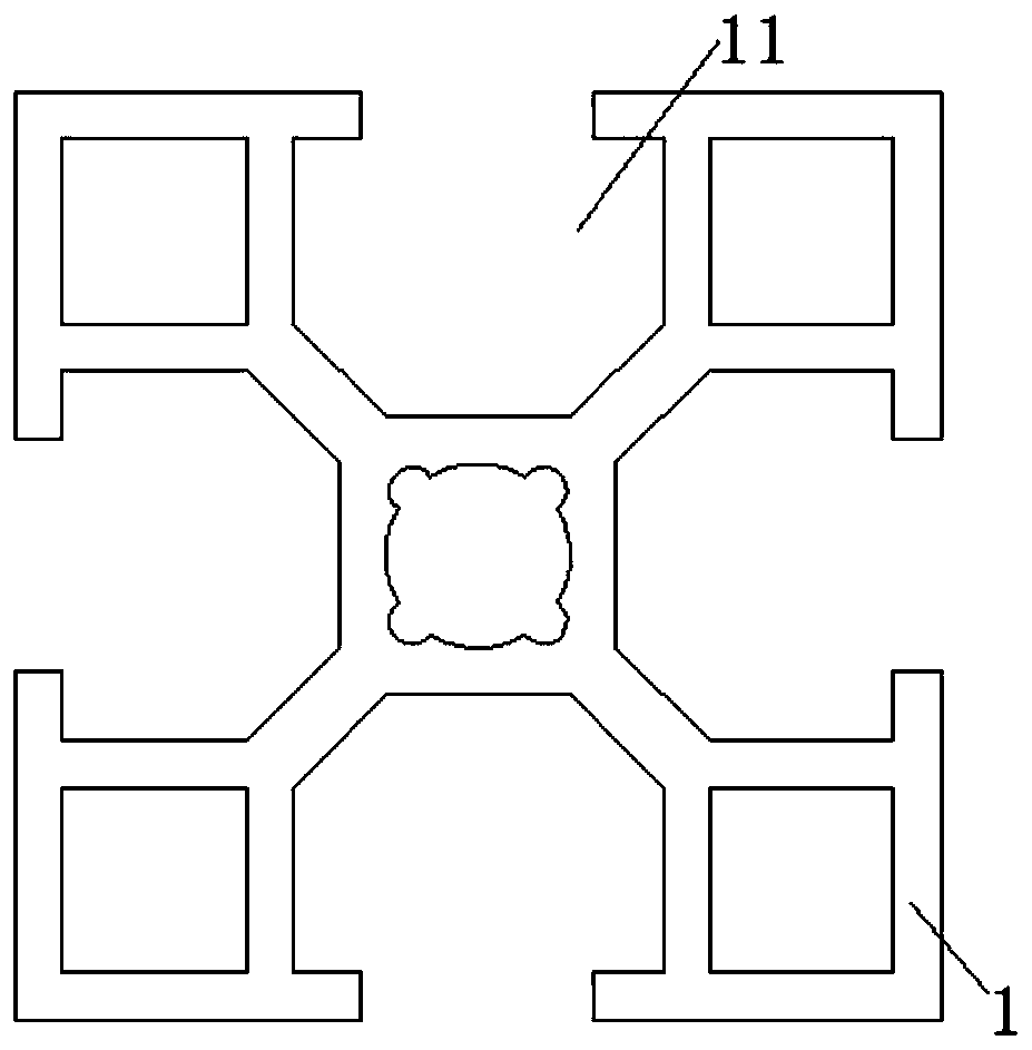
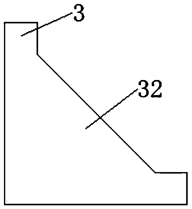
The invention relates to an assembly type television splicing screen mounting device and a mounting method thereof. The assembly type television splicing screen mounting device comprises vertical brackets, transverse brackets, connectors, lifting ropes and splicing screens; the bottoms of the vertical brackets are connected onto the ground; the transverse brackets are parallelly erected between the adjacent vertical brackets; first mounting rails are arranged on the vertical brackets; second mounting rails are arranged on the transverse brackets; one end of each connector is connected with thecorresponding first mounting rail by a first locking piece; the other end of each connector is connected with the corresponding second mounting rail by a second locking piece; one lifting rope is arranged between the two adjacent transverse brackets, and is wound on the transverse bracket on the upper side; one end of each lifting rope is connected with the corresponding transverse bracket on thelower side; a pull handle is arranged at the other end of each lifting rope and the other ends of the lifting ropes extend to the bottoms of the vertical brackets; the splicing screens are connectedwith the second mounting rails by hooks; all the splicing screens are on the same plane. The mounting device and the mounting method have the advantages of convenience in adjusting, high assembling accuracy, convenience in dismounting and mounting, and high safety.

Description

technical field [0001] The present invention relates to the technical field of splicing screens, and more specifically, to a prefabricated TV splicing screen installation device and an installation method thereof. Background technique [0002] The current TV wall is a super-large-screen TV wall composed of multiple screen units, while the conventional TV wall bracket is made by welding alloys on site, or connected by self-tapping screws on the alloy brackets. It is difficult to adjust the achievements, and it is not easy to fix the equipment during the production process. It is difficult to correct the deviation of the bracket. When installing the screen on the top of the TV wall, the staff needs to install the splicing screen units one by one at a high place. The installation is inconvenient and time-consuming. The risk factor is high. Contents of the invention [0003] The problem to be solved by the present invention is to provide a prefabricated TV splicing screen ins...

Claims


Application Information

Patent Timeline
Patent Type & Authority Applications(China)
IPC IPC(8): F16M11/04F16M11/18
Inventor 杨景聪余力健卢伟清罗志彬邝汉兴张文利
Owner GUANGZHOU MECHANICAL & ELECTRICAL INSTALLATION
Learn More