Lead drawing method for valve with lead falling

A valve and valve stem technology, applied in valve devices, engine components, mechanical equipment, etc., can solve problems such as low pumping efficiency, and achieve the effects of rapid pumping, convenient use and simple structure

Inactive Publication Date: 2019-05-03
BAOTOU IRON & STEEL GRP
View PDF4 Cites 1 Cited by
  • Summary
  • Abstract
  • Description
  • Claims
  • Application Information

AI Technical Summary

Problems solved by technology

[0004] The object of the present invention is to provide a method for removing mounds by a valve for removing mounds, which is used to solve the problem of low efficiency of the existing methods for removing mounds

Method used


Image

  • Lead drawing method for valve with lead falling
  • Lead drawing method for valve with lead falling

Examples


Embodiment 1

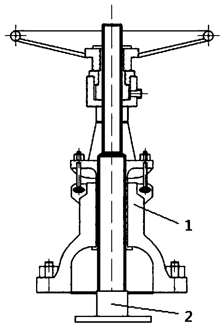
[0016] see figure 1 , a method for removing the weight of the valve, the method is: after removing the valve body part with the waste valve 1, punch a threaded hole at the bottom of the valve stem, and then install a screw 2 on the threaded hole, and install a screw 2 at the bottom of the screw 2 according to the difference of the valve Choose the gasket for the model, let the gasket hang the valve weight that has fallen off, and realize the valve weight to be pulled out.

[0017] The diameter of the threaded hole at the bottom of the valve stem of the above-mentioned valve is 12mm.

[0018] The model of the above screw 2 is M12.


PUM


Abstract

The invention discloses a lead drawing method for a valve with a lead falling. The method comprises the steps that after a valve body is removed from a waste valve, a thread hole is formed in the bottom of a valve rod of the valve in a striking manner, then a thread is installed on the thread hole, a spacer is selected on the bottom of the thread according to the different models of the valve, thespacer hooks the valve lead falling, and the valve lead can be drawn out. The diameter of the thread hole in the bottom of the valve rod of the valve is 12 mm. The method has the following advantagesthat an existing device and tool are utilized, rapid lead drawing is achieved, the structure is simple, and use is convenient.

Description

technical field [0001] The invention relates to a method for extracting mounds, in particular to a method for removing mounds by a valve for removing mounds. Background technique [0002] Due to the year-round operation of the pipeline valves in the power generation operation department of the power supply general plant, the valves are easy to lose weight during operation, resulting in system outages, and due to the long normal pumping time and delay in production, resulting in increased production costs and waste of maintenance time. [0003] Therefore, it is necessary to design a new method of removing mounds to realize fast mound removal. Contents of the invention [0004] The object of the present invention is to provide a method for removing mounds by a valve for removing mounds, which is used to solve the problem of low efficiency of removing mounds in the existing method for removing mounds. [0005] To achieve the above object, the present invention adopts the fol...

Claims


Application Information

Patent Timeline
Patent Type & Authority Applications(China)
IPC IPC(8): F16K51/00
Inventor 才宏
Owner BAOTOU IRON & STEEL GRP
Why Eureka
Try Eureka