
Tunnel protective door structure with electromagnetic door stoppers

A technology for electromagnetic door stoppers and protective doors, which is applied to building structures, fastening devices for wings, mining equipment, etc., can solve the problems of reciprocating shaking of the door body, damage of the door body, and loose closing of the door body, etc. Overhaul and maintenance costs, improve efficiency and success rate, and ensure sufficient isolation

Pending Publication Date: 2019-05-03
CHINA RAILWAY SIYUAN SURVEY & DESIGN GRP
View PDF14 Cites 0 Cited by
  • Summary
  • Abstract
  • Description
  • Claims
  • Application Information

AI Technical Summary

Problems solved by technology

Although the above-mentioned tunnel protective door structure can realize the function of the tunnel protective door to a certain extent, there are many defects, for example: 1, the protective door of the existing tunnel protective door structure is generally locked by the sky and earth lock, and the door body and the door frame It is difficult to form a unified force-bearing body between them, so that when the tunnel protective door is affected by the piston wind, the bolt of the sky and earth lock often needs to bear a large load, which is easily deformed or damaged, resulting in difficulty in opening and closing the tunnel protective door; 2 1. When the existing tunnel protective door is locked, the door body is often not closed tightly, and there is a certain gap between the door frame and the door body, which will not only cause the door body to reciprocate when it is subjected to wind pressure cycles, and cause The damage of the body and the failure of the connection will also cause the tunnel protective door to be too poorly sealed to fully isolate the track area when a fire or other accident occurs in the tunnel, and cannot effectively isolate the smoke or poisonous gas, resulting in unnecessary loss

Method used


Image

  • Tunnel protective door structure with electromagnetic door stoppers
  • Tunnel protective door structure with electromagnetic door stoppers
  • Tunnel protective door structure with electromagnetic door stoppers

Examples


Embodiment Construction

[0035] In order to make the object, technical solution and advantages of the present invention clearer, the present invention will be further described in detail below in conjunction with the accompanying drawings and embodiments. It should be understood that the specific embodiments described here are only used to explain the present invention, not to limit the present invention.

[0036]In addition, the technical features involved in the various embodiments of the present invention described below can be combined with each other as long as they do not constitute a conflict with each other.

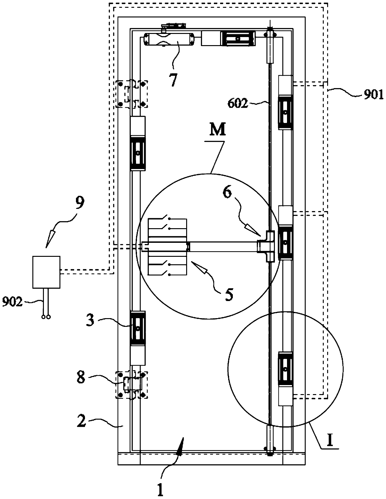
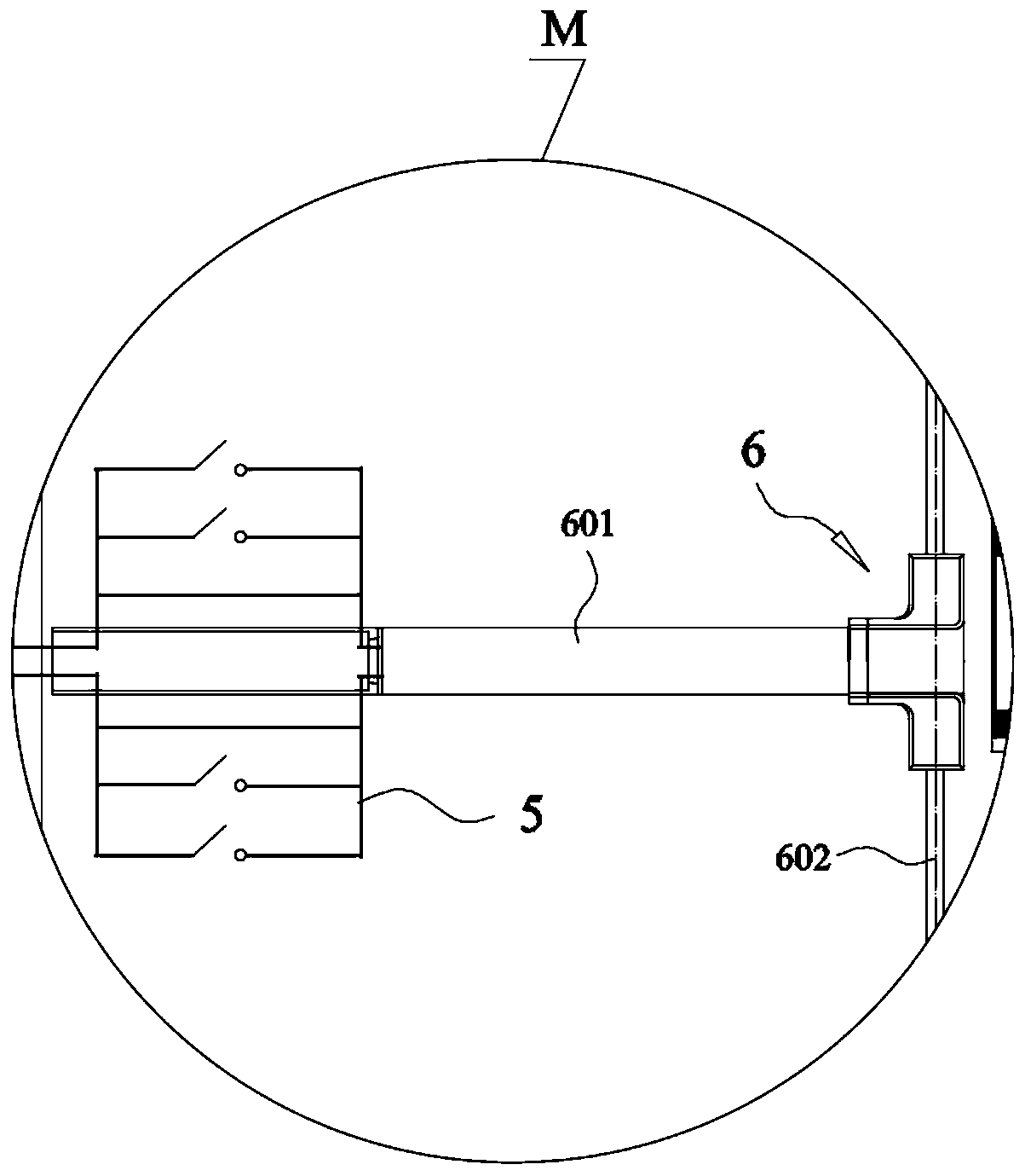
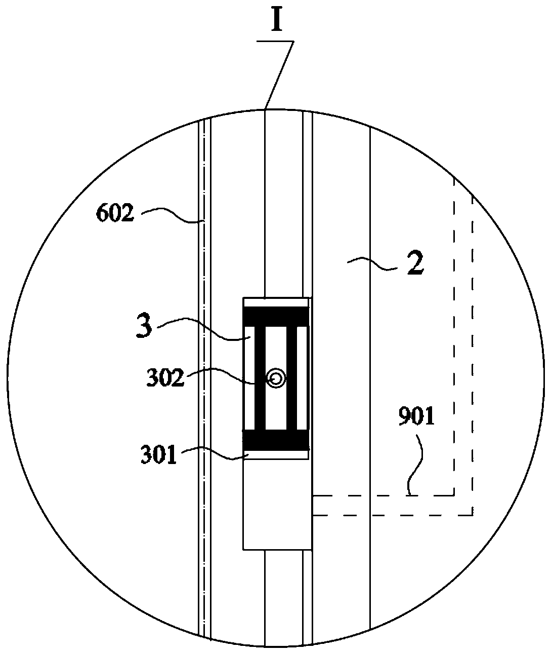
[0037] In the preferred embodiment of the present invention, the structure of the tunnel protective door with electromagnetic door stopper is as follows: Figure 1-8 As shown in , wherein, including the door frame 2 correspondingly connected with the partition wall and the protective door 1 correspondingly connected to the door frame 2 with lateral movement, the protective door 1 is corr...


PUM


Abstract

The invention discloses a tunnel protective door structure with electromagnetic door stoppers, and belongs to the technical field of application of tunnel protective doors. The multiple magnetic doorstoppers are arranged on a door frame with the L-shaped cross section at intervals correspondingly, after a tunnel protective door is closed correspondingly, a door body of the protective door can abut against the magnetic attraction surfaces of the magnetic door stoppers correspondingly, the door body of the protective door is attracted tightly by the multiple magnetic door stoppers, and thus a unified force bearing body can be formed by the protective door and the door frame. The tunnel protective door structure is simple in structure and easy and convenient to arrange, the control accuracyis high, the protective door locked in place and the door frame can be attracted tightly by the multiple magnetic door stoppers, thus double-locking of the protective door is achieved, the unified force bearing body can be formed by the protective door and the door frame correspondingly, shaking when piston wind acts on the protective door is reduced, deformation or damage of related structures ofthe protective door is avoided, the service life of the protective door is prolonged, the overhaul and maintenance costs of the protective door are lowered, and good application and promotion value is achieved.

Description

technical field [0001] The invention belongs to the technical field of tunnel protective doors, and in particular relates to a tunnel protective door structure with an electromagnetic door stopper. Background technique [0002] With the continuous development of my country's high-speed railways, more and more railway tunnels are used, and the mileage is getting longer and longer. During the operation of the tunnel, due to the relatively closed space in the tunnel, it is difficult to deal with a fire in the tunnel, and the evacuation and rescue work of personnel is more difficult than in non-tunnel sections. Therefore, evacuation passages are often added in the tunnel to ensure the efficiency of emergency evacuation, and corresponding tunnel protective doors are set to separate the evacuation passage and the train track area of ​​the tunnel; in addition, communication, signal, power, etc. The storage door openings of the equipment are generally separated from the train track...

Claims


Application Information

Patent Timeline
Patent Type & Authority Applications(China)
IPC IPC(8): E21F17/12E05C19/16
Inventor 耿明张俊岭陈潇张浩邱绍峰史明红殷勤周明翔刘辉王小岑
Owner CHINA RAILWAY SIYUAN SURVEY & DESIGN GRP
Learn More