An embroidery machine color changing red light positioning system and method

A red light positioning and embroidery machine technology, applied in the field of embroidery machines, can solve the problems of cumbersome adjustment of positioning points, difficulty in precise positioning, and tilt deformation, etc., and achieve the effects of improving embroidery precision, adapting to pattern spacing changes, and precise positioning

Active Publication Date: 2020-08-14
浙江镨美科智能刺绣设备有限公司
View PDF10 Cites 0 Cited by
  • Summary
  • Abstract
  • Description
  • Claims
  • Application Information

AI Technical Summary

Problems solved by technology

On the one hand, the process of adjusting the positioning point is cumbersome and difficult. When the cross-shaped positioning replaces the origin positioning, it is even more difficult to adjust; on the other hand, after oblique shooting, the size of the projected reference point will be skewed and deformed, making it difficult to accurately locate

Method used


Image

  • An embroidery machine color changing red light positioning system and method
  • An embroidery machine color changing red light positioning system and method

Examples


Embodiment approach

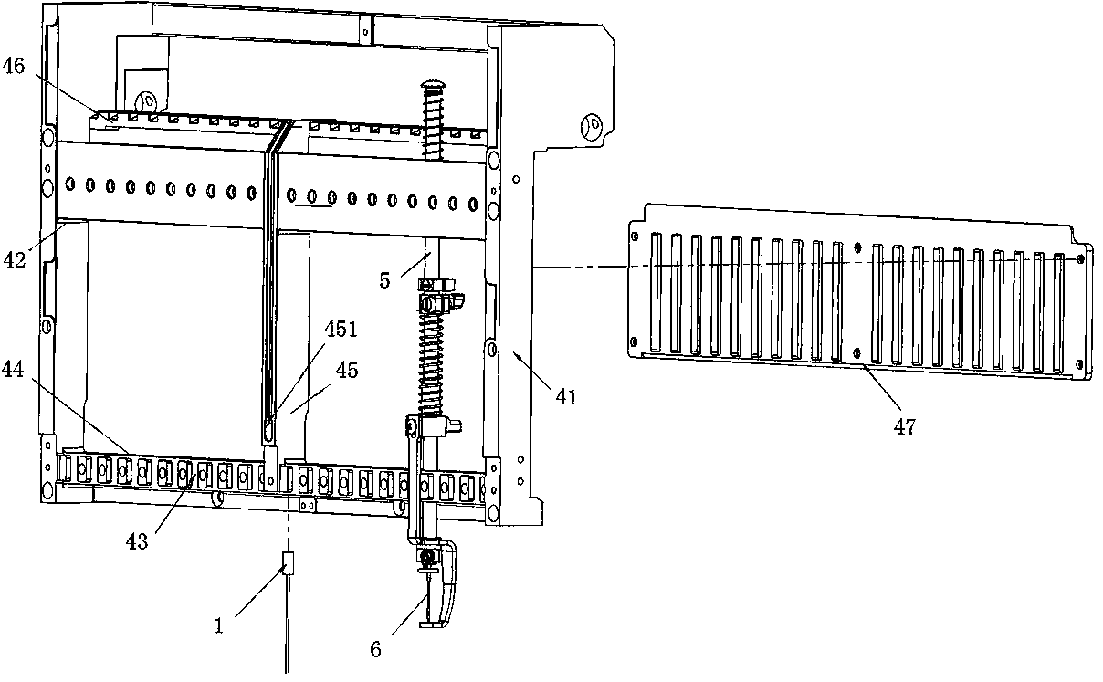
[0031] In one embodiment, the position of the partition 45 on the upper beam 42 is not equal to the distance between the adjacent needle bar holes on both sides, and is not equal to the distance between any adjacent needle bar holes 4 on the upper beam 42 . In another embodiment, the position of the partition 45 on the upper beam 42 is equal to the distance between adjacent needle bar holes on both sides, but not equal to the distance between any adjacent needle bar holes 4 on the upper beam 42 . In another embodiment, one end of the partition 45 is fixedly installed on the upper beam 42, and the other end is fixedly installed on the lower beam 43. The distance between the position of the partition 45 on the upper beam 42 and the adjacent needle bar holes 44 on both sides is equal to that of the upper beam. 42 the spacing between any adjacent needle bar holes 44. The distance between the position of the partition 45 on the lower beam 43 and the adjacent needle bar holes 44 on ...


PUM


Abstract

The invention discloses an embroidery machine color changing and infrared-light positioning system, and belongs to the technical field of embroidery machines. The system comprises an infrared positioning device, a color changing box and a color changing pull rod; the color changing pull rod is connected with a needle bar frame through a color changing bracket; the color changing box is arranged ona rack cross beam of the needle bar frame and used for controlling the color changing pull rod to drive the needle bar frame to move left and right; a lower cross beam of a frame body of the needle bar frame is provided with the infrared positioning device, so that the infrared positioning device and a needle bar are distributed on a straight line, and a vertical positioning light source is emitted. The system is adopted for the method, and the method comprises the steps that when the color changing box executes a color changing instruction, the needle bar frame is controlled to move to a needle position where the infrared positioning device is arranged according to color changing code parameters, and starting and stopping of the infrared positioning device are triggered. The embroidery machine color changing and infrared-light positioning system and method are precise in positioning and not limited to fixing and positioning of one embroidery needle; moreover, color changing and positioning systems are combined into one system, an embroidery control system is simplified, and the embroidery efficiency is improved.

Description

technical field [0001] The invention belongs to the technical field of embroidery machines, in particular to an embroidery machine color-changing red light positioning system and method. Background technique [0002] The traditional embroidery positioning method after printing: mark the printing point on the stretch cloth frame, and fix a thumbtack or a pin on the printing point to determine the printing position. Due to the many operation steps and easy to be scratched, the production is greatly affected. restrict. For this reason, existing embroidery positioning method is to realize by infrared ray positioning embroidery. [0003] For example, the invention patent CN201424578Y discloses an infrared ray positioning device for a computerized embroidery machine. The infrared ray positioning lamp is arranged on the hanger parallel to the top of the stretch cloth frame, and the infrared ray positioning light on the hanger is adjusted so that the light spot of the infrared ray ...

Claims


Application Information

Patent Timeline
Patent Type & Authority Patents(China)
IPC IPC(8): D05C13/02D05C11/16
Inventor 陈天龙陈天池方狄永蔡洁钟
Owner 浙江镨美科智能刺绣设备有限公司
Why Eureka
Try Eureka