Housing, method for controlling test of photosensitive test module, and electronic equipment

A technology for testing modules and electronic equipment, which is applied to electrical equipment shells/cabinets/drawers, optics, electrical components, etc., and can solve problems such as electronic equipment that needs to be improved

Inactive Publication Date: 2019-04-30
GUANGDONG OPPO MOBILE TELECOMM CORP LTD
View PDF4 Cites 4 Cited by
  • Summary
  • Abstract
  • Description
  • Claims
  • Application Information

AI Technical Summary

Problems solved by technology

[0004] However, the current casing with photosensitive test module, the method for controlling the photosensitive test module test, and the electronic equipment still need to be improved.

Method used


Image

  • Housing, method for controlling test of photosensitive test module, and electronic equipment
  • Housing, method for controlling test of photosensitive test module, and electronic equipment
  • Housing, method for controlling test of photosensitive test module, and electronic equipment

Examples


Embodiment Construction

[0024] Embodiments of the invention are described in detail below, examples of which are illustrated in the accompanying drawings. The embodiments described below by referring to the figures are exemplary and are intended to explain the present invention and should not be construed as limiting the present invention.

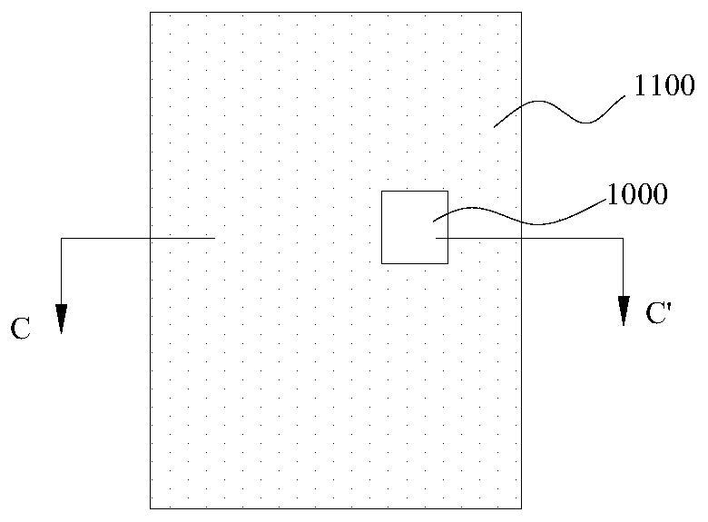
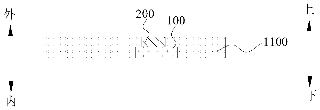
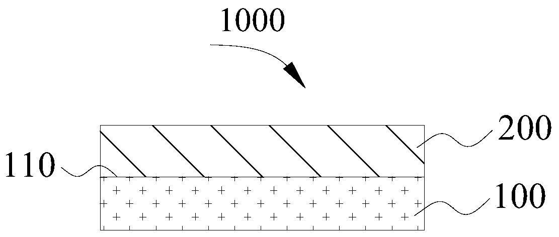
[0025] In one aspect of the invention, the invention proposes a housing. According to an embodiment of the present invention, refer to figure 1 as well as figure 2 ( figure 2 for along figure 1 The cross-sectional view of CC' direction in the center), the housing includes: a base body 1100 and a photosensitive test module 1000, and the photosensitive test module 1000 is arranged on the base body 1100, for reference image 3 , the photosensitive test module 1000 includes: a photosensitive component 100 and an electrochromic component 200, wherein the electrochromic component 200 is arranged toward the outside of the substrate 1100 (ie, the "outside" directio...


PUM


Abstract

The invention discloses a housing, a method for controlling the test of a photosensitive test module, and a piece of electronic equipment. Specifically, the housing includes a substrate and a photosensitive test module arranged on the substrate. The photosensitive test module includes a photosensitive component which has a detection surface, and an electrochromic component which at least covers the detection surface of the photosensitive component and is configured to be switched between a high light transmittance state and a low light transmittance state. The light transmittance of the electrochromic module is not less than 85% in the high light transmittance state. Thus, the photosensitive test module has a good appearance effect and use performance, and the surface consistency and integrity of the housing can be improved.

Description

technical field [0001] The invention relates to the field of smart device manufacturing, in particular to a housing, a method for controlling photosensitive test module testing, and electronic equipment. Background technique [0002] The optical sensor is an optical detection device that can detect optical signals and convert the optical signals into electrical signals or other required forms of information output according to certain rules, so as to meet the requirements of information transmission, processing, storage, display, recording and control requirements. Light sensors are mainly divided into ambient light sensors, infrared light sensors, sunlight sensors, ultraviolet light sensors, etc. With the development of laser technology, the application of light sensors is becoming more and more extensive. For example, light sensors can be used in the fields of automobiles, intelligent lighting systems, intelligent electronic equipment, and intelligent medical equipment. ...

Claims


Application Information

Patent Timeline
Patent Type & Authority Applications(China)
IPC IPC(8): H05K5/02G02F1/163
CPCG02F1/163H05K5/0243
Inventor 杨鑫
Owner GUANGDONG OPPO MOBILE TELECOMM CORP LTD
Why Eureka
Try Eureka