Vehicle-mounted radar antenna

A vehicle-mounted radar and antenna technology, applied in antennas, antenna arrays, antenna components, etc., to solve problems such as low operating frequency bands

Active Publication Date: 2019-04-26
NINGBO UNIV
View PDF10 Cites 2 Cited by
  • Summary
  • Abstract
  • Description
  • Claims
  • Application Information

AI Technical Summary

Problems solved by technology

For vehicle-mounted radar antennas, there are many design schemes at home and abroad, but most of these vehicle-mounted radar anten...

Method used


Image

  • Vehicle-mounted radar antenna
  • Vehicle-mounted radar antenna
  • Vehicle-mounted radar antenna

Examples


Embodiment 1

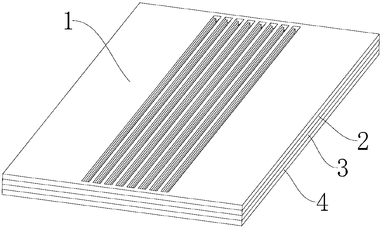
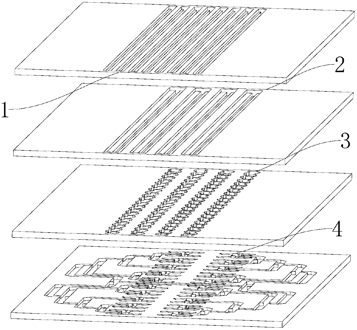
[0029] Embodiment one: if figure 1 with figure 2 As shown, a vehicle-mounted radar antenna includes a radiation layer 1, a planar waveguide power layer 2, a mode conversion layer 3, and a feed network layer 4 arranged in sequence from top to bottom. The feed network layer 4 outputs multiple TE10 mode signals , the energy distribution of the multiple TE10-mode signals output by the feed network layer 4 is approximately Taylor distribution, and the mode conversion layer 3 is used to convert each TE10-mode signal output by the feed network layer 4 into a quasi-TEM mode line source signal for transmission Give the slab waveguide power layer 2, the slab waveguide power layer 2 divides each quasi-TEM model line source signal into two and sends it to the radiation layer 1, and the radiation layer 1 radiates plane waves outward.

Embodiment 2

[0030] Embodiment two: this embodiment is generally the same as embodiment one, and the difference is as follows:

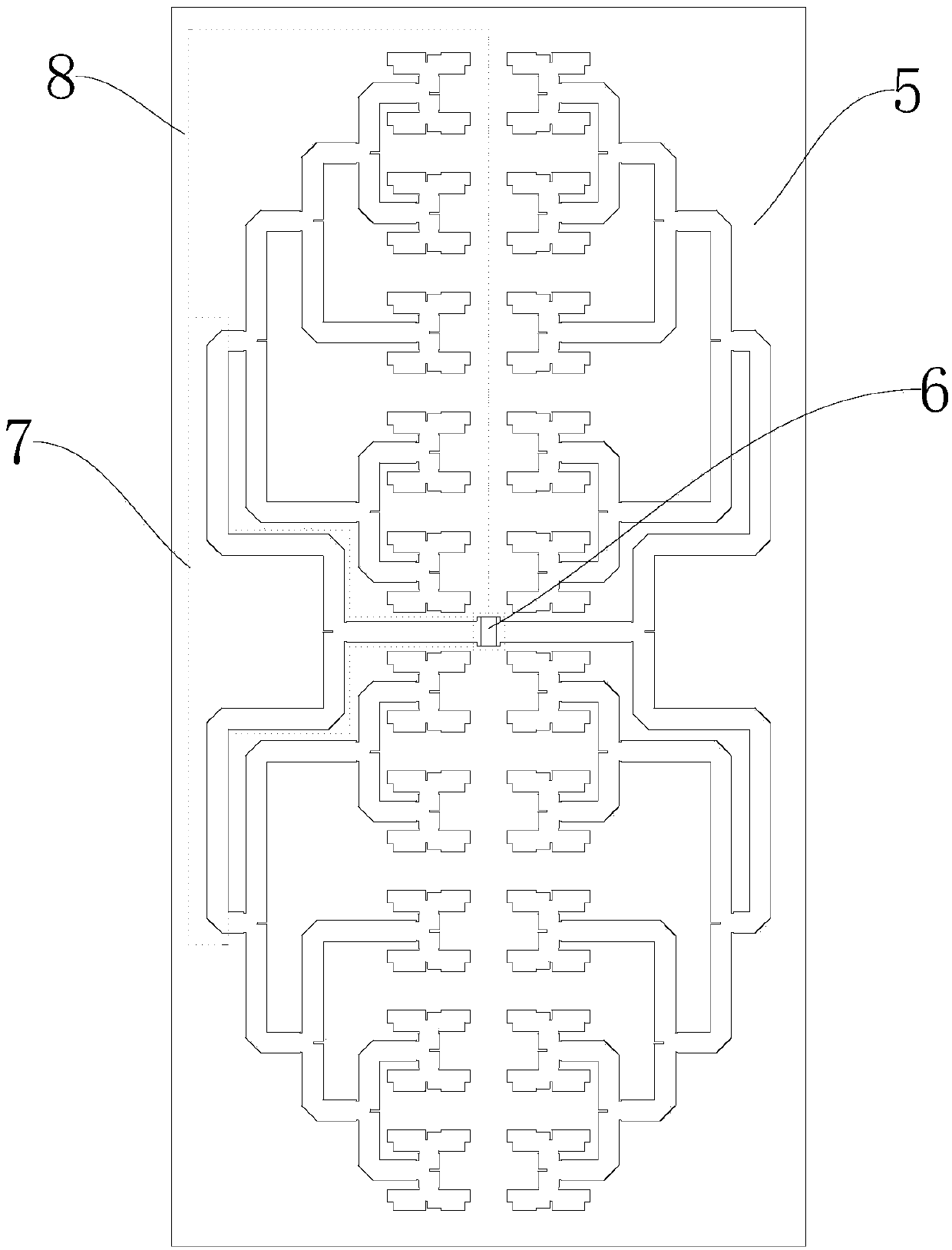
[0031] Such as image 3 As shown, in this embodiment, the feed network layer 4 includes a first metal plate 5 and a first E-plane waveguide power divider 6, two H-plane waveguide power dividers 7 and Four H-plane T-shaped waveguide power divider networks 8; the first E-plane waveguide power divider 6 has an input terminal, a first output terminal and a second output terminal, and each H-plane waveguide power divider 7 has an input terminal, a first output terminal, and a second output terminal respectively. An output terminal and a second output terminal, each H-plane T-shaped waveguide power distribution network 8 has an input terminal, a first output terminal, a second output terminal, a third output terminal, a fourth output terminal and a fifth output terminal; The four H-plane T-shaped waveguide power distribution networks 8 are distributed in a manner of 2...


PUM

PropertyMeasurementUnit
Lengthaaaaaaaaaa
Lengthaaaaaaaaaa
Return lossaaaaaaaaaa

Abstract

The invention discloses a vehicle-mounted radar antenna. The vehicle-mounted radar antenna comprises a radiation layer, a slab waveguide power distribution layer, a mode conversion layer and a feedingnetwork layer which are sequentially arranged from top to bottom, wherein the feeding network layer outputs multichannel TE10 mode signals, the energy distribution of the multichannel TE10 mode signals output by the feeding network layer is approximate to Taylor distribution, and the mode conversion layer is used for separately converting each channel of the corresponding TE10 mode signal outputby the feeding network layer into a quasi-TEM mode line source signal and sending the quasi-TEM mode line source signals to the slab waveguide power distribution layer, each channel of the corresponding quasi-TEM mode line source signal is divided into two parts by the slab waveguide power distribution layer and then sent to the radiation layer, and the radiation layer radiates planar waves outwards. The radar antenna has the advantages that the working frequency band is high on the basis of a low profile and a high gain.

Description

technical field [0001] The invention relates to an antenna, in particular to a vehicle radar antenna. Background technique [0002] With the continuous improvement of people's living standards, the number of private cars is increasing. However, while private cars bring convenience to people's lives, they also bring about serious traffic safety problems. Unmanned driving technology is the trend of safe driving in the future. Advanced Driver Assistance Systems (ADAS, Asvanced Driver Assistance Systems) is a key technology connecting active safety and unmanned driving. The millimeter wave vehicle radar system is a key part of the advanced assisted driving system. It is used to provide lane change assistance, adaptive cruise and collision warning, etc., and plays an important role in improving driving comfort and reducing the accident rate. One of the key components of the millimeter wave vehicle radar system is the vehicle radar antenna. Automotive radar antennas require hig...

Claims


Application Information

Patent Timeline
IPC IPC(8): H01Q1/32H01Q1/36H01Q1/50H01Q3/06H01Q21/00H01Q21/12
CPCH01Q1/3233H01Q1/36H01Q1/50H01Q3/06H01Q21/0006H01Q21/12
Inventor 尤阳黄季甫方陈剑张乘峰周国良尤清春陆云龙钟硕敏
Owner NINGBO UNIV
Why Eureka
Try Eureka