An intelligent guard system and a guard method
An intelligent, target object technology, applied in the field of intelligent duty systems, can solve the problems of not being able to accurately locate, lock, drive away or restrict illegal targets, and unable to meet the needs of intelligent security guards.
- Summary
- Abstract
- Description
- Claims
- Application Information
AI Technical Summary
Problems solved by technology
Method used
Image
Examples
Embodiment 1
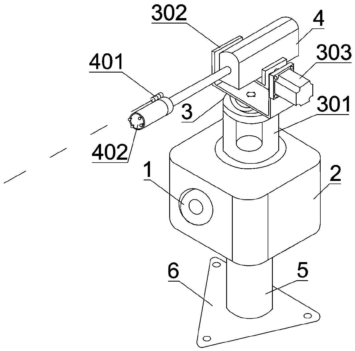
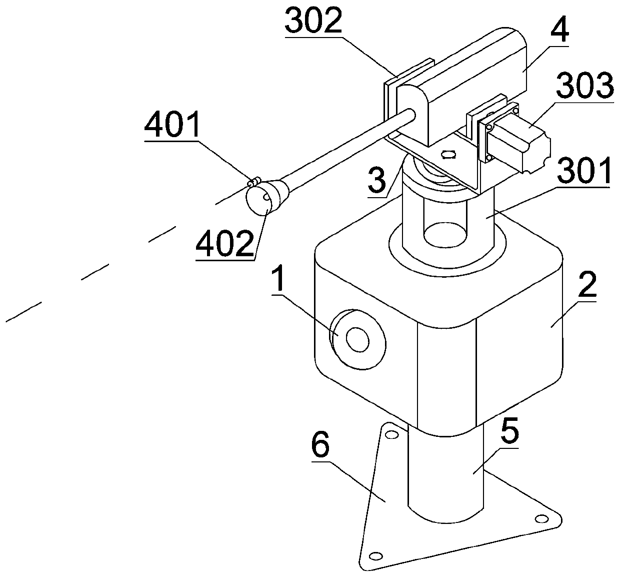
[0080] Such as figure 1 As shown, an intelligent duty guard system includes an imaging device 1, a processing part 2, a locking moving part 3, a limiting part 4, a support column 5, a connecting piece 6 and a data transmission unit 7; the locking moving part 3 includes an X-axis motor 301, Support 302, Y-axis motor 303, support 302 is connected with the rotating shaft of X-axis motor 301, and Y-axis motor 303 is arranged on the support 302; Limiting part 4 is a net-catching transmitter, including target locking point member 401, net-catching launching head 402 , a launch switch, a launch component, and the target locking point component 401 is an external laser calibrator. One end of the support column 5 is connected to the processing unit 2 , and the other end is connected to the connecting piece 6 . The image detection area of the imaging device 1 is a guard area. The data transmission unit 7 is connected to the user terminal via a wireless network, and the user terminal...
Embodiment 2
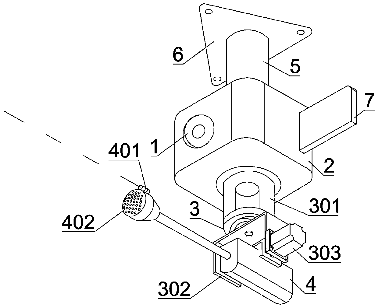
[0119] Such as figure 2 As shown, a kind of intelligent on-duty system includes an imaging device 1, a processing part 2, a locking moving part 3, a limiting part 4, a support column 5, a connecting piece 6, and an external display 7; the locking moving part 3 includes an X-axis motor 301, a bracket 302, Y-axis motor 303, the support 302 is connected with the rotating shaft of the X-axis motor 301, and the Y-axis motor 303 is arranged on the support 302; the limiting part 4 includes the target locking point member 401, odorous water or stimulating gas emission head, emission switch, The emitting component 402 and the target locking point component 401 are external laser collimators. One end of the support column 5 is connected to the processing unit 2 , and the other end is connected to the connecting piece 6 . The image detection area of the imaging device 1 is a guard area. The intelligent on-duty system is fixed on the wall through the supporting column 5 and the conne...
Embodiment 3
[0157] Such as figure 1 As shown, an intelligent duty guard system includes an imaging device 1, a processing part 2, a locking moving part 3, a limiting part 4, a support column 5, and a connecting part 6; the locking moving part 3 includes an X-axis motor 301, a bracket 302, and a Y-axis Motor 303, support 302 is connected with the rotating shaft of X-axis motor 301, and Y-axis motor 303 is arranged on the support 302; Limiting part 4 is a strong light illuminator, includes target locking point member 401, strong light lamp head 402, emission switch, emission member , the target locking point component 401 is an external laser sight. One end of the support column 5 is connected to the processing unit 2 , and the other end is connected to the connecting piece 6 . The image detection area of the imaging device 1 is a guard area.
[0158] The imaging device 1 is used to take images of the image detection area; the processing unit 2 is connected to the imaging device 1, auto...
PUM
 Abstract
Description
Claims
Application Information
 - R&D
- Intellectual Property
- Life Sciences
- Materials
- Tech Scout
- Unparalleled Data Quality
- Higher Quality Content
- 60% Fewer Hallucinations
Browse by: Latest US Patents, China's latest patents, Technical Efficacy Thesaurus, Application Domain, Technology Topic, Popular Technical Reports.
© 2025 PatSnap. All rights reserved.Legal|Privacy policy|Modern Slavery Act Transparency Statement|Sitemap|About US| Contact US: help@patsnap.com


