Side-entering type backlight module and liquid crystal display device and backlight plate optical inspection method

An edge-type backlight and backlight plate technology, applied in the field of optical inspection of light guide plates, can solve the problems of touching and moving light guide plates, contamination of light guide plates, enterprise losses, etc., to reduce costs, facilitate transportation, and save costs.

Inactive Publication Date: 2019-04-26
QINGDAO TECHNOLOGICAL UNIVERSITY
View PDF0 Cites 1 Cited by
  • Summary
  • Abstract
  • Description
  • Claims
  • Application Information

AI Technical Summary

Problems solved by technology

The price of a light guide plate ranges from 50-1500 yuan, which is a big loss
In addition, experienced employees will intentionally push the light guide plate toward the light bar when inspecting the light guide plate, so as to reduce the distance between the light bar and the light-incident side of the light guide plate. Although this can improve the optical detection value of the light guide plate, it cannot Avoid touching the moving light guide plate, causing stains and scratches on the light guide plate, especially for 86-inch (1.9m*1.2m) or larger light guide plates, it is difficult to move at all
The above problems will cause the loss of the enterprise

Method used


Image

  • Side-entering type backlight module and liquid crystal display device and backlight plate optical inspection method
  • Side-entering type backlight module and liquid crystal display device and backlight plate optical inspection method
  • Side-entering type backlight module and liquid crystal display device and backlight plate optical inspection method

Examples


Embodiment 1

[0046] Embodiment 1 provides a side-entry backlight module, which includes a backlight panel main body, a light source, a light source moving module, and a shading module.

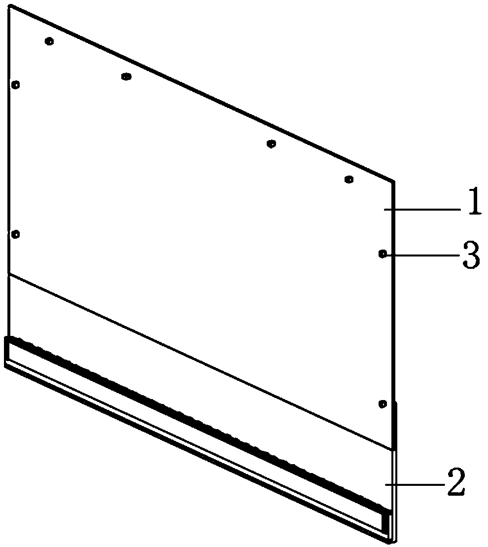
[0047] Please refer to the attachedfigure 1 The main body of the backlight panel includes a first substrate 1 and a second substrate 2 for fixing the light guide plate to be inspected, and the first substrate 1 and the second substrate 2 are detachably connected to form other components of the backlight module , such as the accommodation space for the light source, the light source moving module and the shading module; the first substrate 1 and the second substrate 2 connected in a detachable manner are not integral structures and can be placed separately during transportation for convenient transportation.

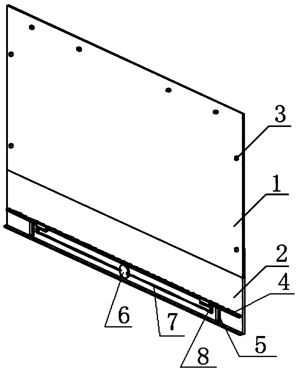
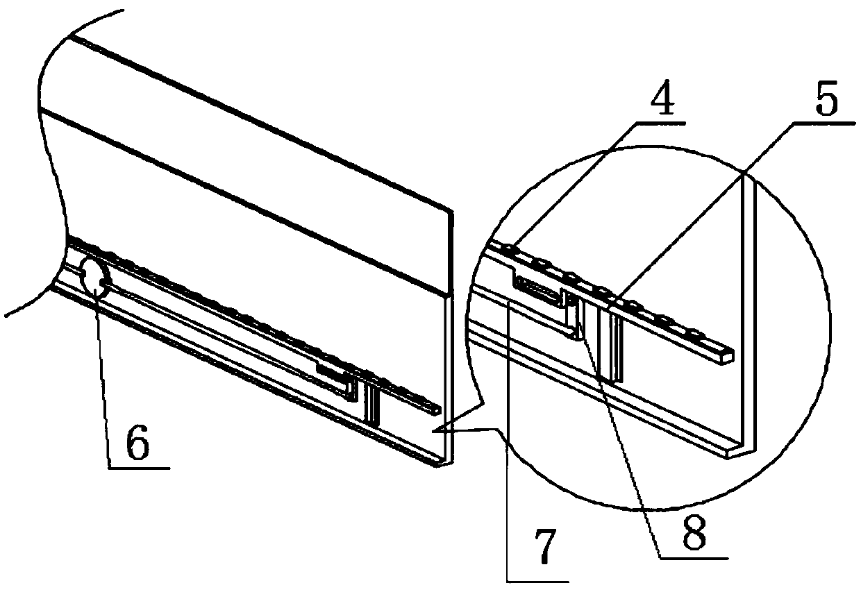
[0048] Please refer to attached figure 2 and image 3 , the light source moving module is arranged on the front side of the second substrate 2, the light source moving module includes a light source...

Embodiment 2

[0061] This embodiment provides a liquid crystal display device, which includes a light guide plate and the above-mentioned edge-type backlight module. The light guide plate is fixed on the first substrate 1 and is arranged opposite to the light source 4 .

[0062] Wherein, for the specific structure of the side-type backlight module of this embodiment, please refer to the relevant descriptions of the previous embodiments, and details are not repeated here.

[0063] It should be noted that, in this embodiment, the light guide plate is fixedly installed on the first substrate through a plurality of positioning pins 3. In this embodiment, a plurality of positioning pins 3 are used to fix the light guide plate on the first substrate. The positioning pins 1 Cooperate with the card slot of the light guide plate to ensure that the light guide plate will not shake on the first substrate.

Embodiment 3

[0065] This embodiment provides an optical inspection method for a light guide plate, which is implemented based on the above-mentioned side-entry backlight module, and the method includes the following steps:

[0066] S101, fixing and installing the light guide plate to be inspected on the first substrate through a plurality of positioning pins;

[0067] S102, turning the knob clockwise, the knob drives the turntable 6 to rotate;

[0068] S103, the turntable drives two L-shaped levers 8 to make a fan-shaped movement around the rotating shaft 10 through the two connecting rods 7;

[0069] S104, the projections 83 of the two L-shaped levers respectively fan-shaped swing, and at the same time jack up the light source support frame 5;

[0070] S105, the light source support frame 5 drives the light source 4 to move upward in a direction perpendicular to the light source support frame 5, so that the light source is close to the light incident side of the light guide plate;

[00...


PUM


Abstract

The invention discloses a side-entering backlight module and a liquid crystal display device and a backlight plate optical inspection method. The backlight module comprises a backlight plate main body, wherein the backlight plate main body comprises a first substrate used for bearing a light guide plate to be inspected and a second substrate detachably connected with the first substrate, the second substrate is provided with a light source moving module, and the light source moving module is provided with a light source. According to the invention, the light source moving module is adopted todrive the light source to move in the direction perpendicular to the light source moving module, so that the distance between the light source and the light guide plate is adjusted, the phenomenon that the optical index is not qualified due to the distance problem between the incident side of the light guide plate and the light source is avoided, namely, the misjudgment probability of whether thelight guide plate is qualified or not is reduced, in the process, the light guide plate does not need to be touched and moved, the pollution and scratch of the light guide plate cannot be caused, theloss is reduced, the cost is saved, and the backlight plate main body is not an integral structure, so that the transportation is convenient.

Description

technical field [0001] The disclosure belongs to the field of optical inspection of light guide plates, and in particular relates to a side-entry backlight module for inspecting light guide plate optics with adjustable light bar distances, a liquid crystal display device using the backlight module, and a backlight using the side-entry backlight module. Board optical inspection method. Background technique [0002] The rapid development of my country's liquid crystal display industry has driven the development of many enterprises producing liquid crystal backlight module components. The backlight module is divided into side-type backlight and direct-type backlight. The present disclosure is directed to a backlight module of an edge-lit backlight. [0003] The main component of the backlight module of the side-lit backlight is the light guide plate. After ink printing or laser dotting, the light guide plate needs to be inspected optically. The optical inspection is usually ...

Claims


Application Information

Patent Timeline
IPC IPC(8): G02F1/13357G02F1/13G01M11/02
CPCG02F1/1309G02F1/133615G01M11/00G01M11/0207
Inventor 吕强强孙树峰王萍萍邵晶刘庆玉王津王永武王德祥
Owner QINGDAO TECHNOLOGICAL UNIVERSITY
Why Eureka
Try Eureka