
Refrigerating unit and combined type refrigerating device thereof

A technology of refrigeration units and refrigeration devices, which is applied in the direction of refrigerators, refrigeration and liquefaction, and the operation mode of machines, etc. It can solve the problems of inability to realize heat transfer, low heat dissipation power and temperature span, and inability to meet the requirements of device refrigeration.

Active Publication Date: 2019-04-26
ZHENGZHOU UNIV
View PDF6 Cites 0 Cited by
  • Summary
  • Abstract
  • Description
  • Claims
  • Application Information

AI Technical Summary

Problems solved by technology

At present, the main problem of electrocaloric effect refrigeration based on materials with electrocaloric effect is that the existing electrothermal effect refrigeration devices cannot achieve continuous heat transfer due to the limitation of the application and removal time of the electric field, so the heat dissipation power and temperature span are low, which cannot meet the requirements. Practical application of device cooling requirements

Method used


Image

  • Refrigerating unit and combined type refrigerating device thereof
  • Refrigerating unit and combined type refrigerating device thereof
  • Refrigerating unit and combined type refrigerating device thereof

Examples


Embodiment 1

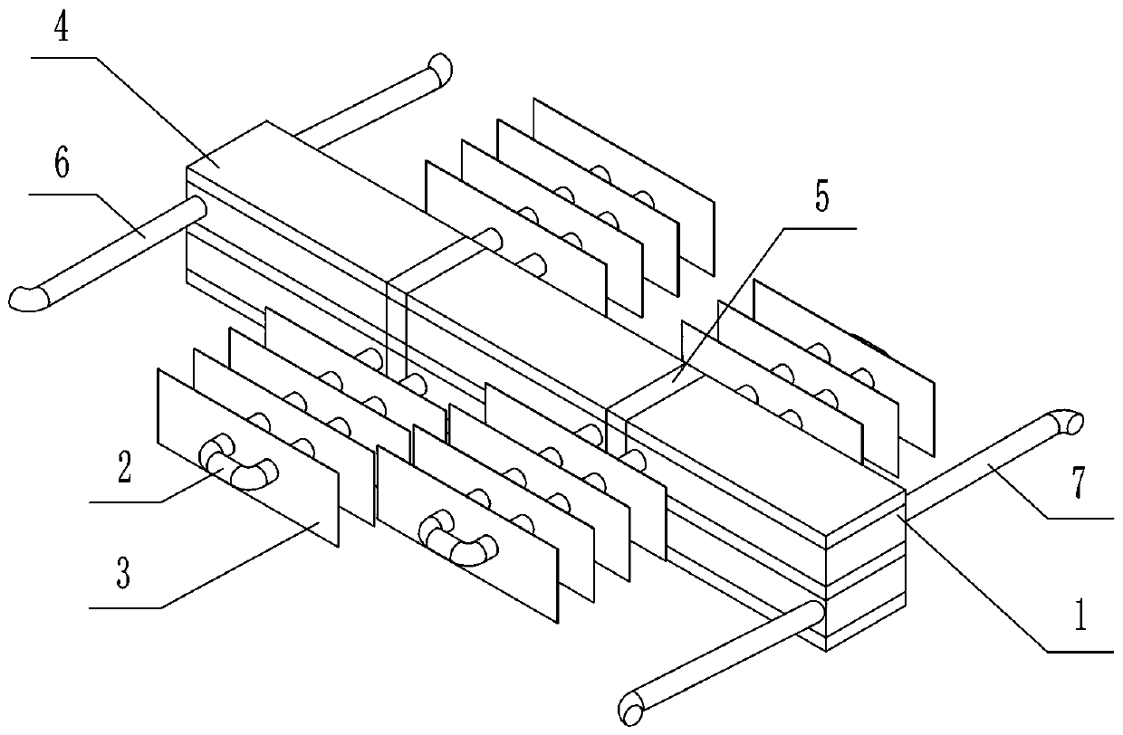
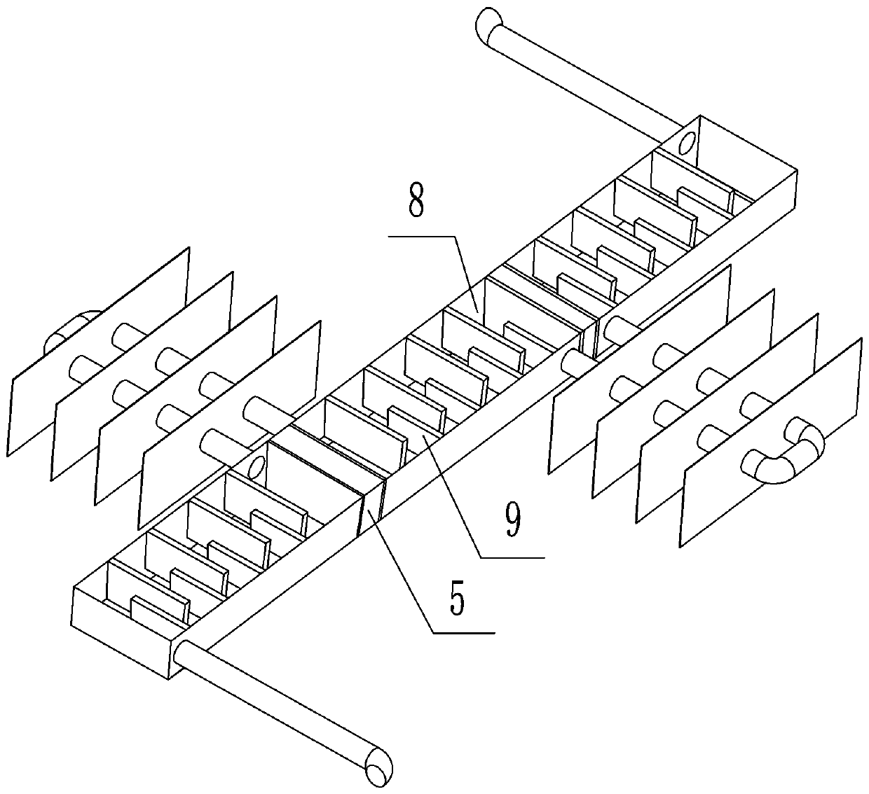
[0039] This embodiment provides a refrigeration unit, such as figure 1 and figure 2As shown, it includes electrothermal material layer 4 with electrocaloric effect, heat carrying layer 1, low thermal conductivity fluid, high thermal conductivity fluid and power supply. The heat carrying layer 1 is attached to the surface of the electrothermal material layer 4 .

[0040] The heat-carrying layer 1 includes a multi-section flow channel 8 and a plurality of flow dividing partitions 9 arranged inside the flow channel 8 ; two adjacent flow channels 8 are separated by an insulating material 5 . Heat dissipation pipelines 2 are alternately arranged on both sides of the adjacent two flow channels 8 and communicated through the heat dissipation pipelines 2. A plurality of heat dissipation fins 3 are arranged on the heat dissipation pipelines 2; the flow channels 8 The two ends of the pipe are respectively provided with a liquid inlet pipe 6 and a liquid outlet pipe 7.

[0041] The e...

Embodiment 2

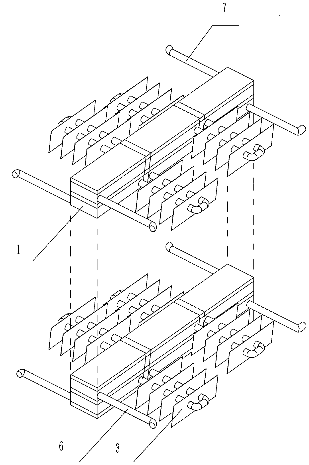
[0044] This embodiment provides a refrigeration unit combination composed of the refrigeration unit described in Embodiment 1, such as image 3 As shown, it includes a multilayer electrothermal material layer 4 and a multilayer heat carrying layer 1 . The heat-carrying layer and the electrothermal material layer are alternately laid up and down; the flow direction of the high heat-conducting fluid in the heat-carrying layers of two adjacent layers is opposite.

Embodiment 3

[0046] This embodiment provides a refrigeration unit combination composed of the refrigeration unit described in Embodiment 1, such as Figure 4 As shown, it includes a multilayer electrothermal material layer 4 and a multilayer heat carrying layer 1 . The heat-carrying layer and the electrothermal material layer are alternately laid left and right; the flow direction of the high heat-conducting fluid in the heat-carrying layers of two adjacent layers is opposite.


PUM


Abstract

The invention provides a refrigerating unit. An electric heating material layer, a heat carrying layer, low heat conduction fluid, high heat conduction fluid and a power source are included; the heatcarrying layer and the electric heating material layer are arranged in a stacked manner; the heat carrying layer comprises a plurality of segments of flow channels partitioned by an insulating heat-insulating material; the flow channels sequentially communicate with one another through heat dissipating pipelines on the two sides; the electric heating material layer comprises a plurality of segments of refrigerating pieces partitioned by an insulating heat-insulating material, and the refrigerating pieces correspond to the flow channels in one-to-one correspondence; the heat carrying layer is alternately filled with the low heat conduction fluid and the high heat conduction fluid, and pulse type marching is performed; the refrigerating pieces are controlled according to the regulated electric field increasing sequence and the regulated electric field decreasing sequence, so that refrigerating can be achieved; and the refrigerating unit can transmit heat and cooling capacity generated bythe refrigerating pieces to the heat carrying layer, and one-way transmission of heat can be achieved. The invention further provides a refrigerating device composed of the plurality of refrigeratingunits stacked transversely or vertically or stereoscopically. The refrigerating device can be used for continuously transmitting heat, and can improve the heat dissipating power and the temperature span.

Description

technical field [0001] The invention relates to the field of solid refrigeration, in particular to a refrigeration unit and a combined refrigeration device. Background technique [0002] At present, domestic and foreign research on the use of electrothermal effect for refrigeration mainly focuses on the development of materials with high electrothermal effect, such as PbZrTiO3 thin film and BaTiO3, as well as other thin film ceramics and polymers. With the development of the economy, devices are developing toward miniaturization, especially the refrigeration technology in electronic equipment is particularly important. Electronic chips will generate a lot of heat during the working process, and the accumulation of heat will cause chip failure and damage. According to investigations and research, more than half of the current electronic device damage is caused by thermal failure. Therefore, timely heat dissipation of electronic devices is the key Necessary safeguards to ensu...

Claims


Application Information

Patent Timeline
Patent Type & Authority Applications(China)
IPC IPC(8): F25B21/00
CPCF25B21/00F25B2321/001Y02B30/00
Inventor 孟祥睿孟奕彤
Owner ZHENGZHOU UNIV
Learn More