Anti-deformation pouring mold for building supporting column and pouring construction method thereof

A support column and anti-deformation technology, which is applied in the direction of construction, building structure, formwork/formwork/work frame, etc., can solve the problems of bulge on the surface of the column and affect the pouring quality of the column, so as to improve the quality of pouring and improve the application Range, an effect that increases edge strength

Inactive Publication Date: 2019-04-26
青建集团股份公司
View PDF0 Cites 0 Cited by
  • Summary
  • Abstract
  • Description
  • Claims
  • Application Information

AI Technical Summary

Problems solved by technology

The existing pouring molds for building support columns generally adopt the form of four templates enclosing a column-shaped pouring space. During the pouring process, due to the extrusion of the concrete from the inside to the outside, the pouring mold will be deformed after being under pressure. , making the surface of the column after pouring bulge, which affects the pouring quality of the column

Method used


Image

  • Anti-deformation pouring mold for building supporting column and pouring construction method thereof
  • Anti-deformation pouring mold for building supporting column and pouring construction method thereof
  • Anti-deformation pouring mold for building supporting column and pouring construction method thereof

Examples


Embodiment 1

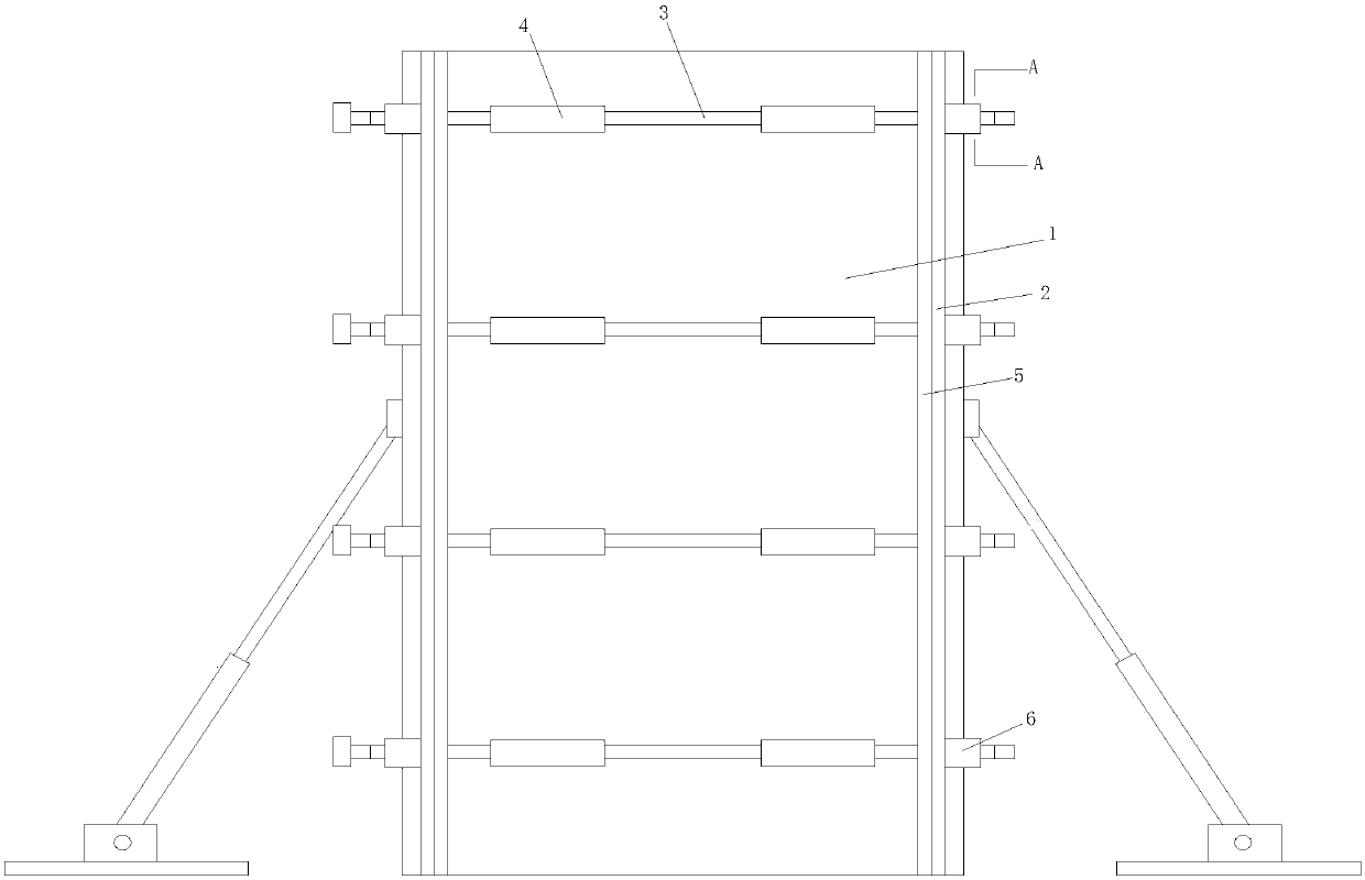
[0040] Such as Figure 1-Figure 3 As shown, the present invention is an anti-deformation pouring form for building support columns, which includes two parallel inner formworks 1 and two parallel outer formworks 2, the two inner formworks 1 and two outer formworks 2 form a prism shaped pouring space, the inner formwork 1 is set between two outer formworks 2 and is perpendicular to the outer formwork 2, the side edge of the inner formwork 1 is in contact with the outer formwork 2; the outer surface of the outer formwork 2 is provided with an inner formwork The fixed support assembly, the inner formwork fixed support assembly passes through the outer plate and is fixedly connected with the outer surface of the inner formwork 1; the outer formwork support assembly is arranged on the outer surface of the outer formwork 2, and the outer formwork support assembly extends along the length of the outer formwork 2 Orientation settings.

[0041] In the technical solution of the present ...

Embodiment 2

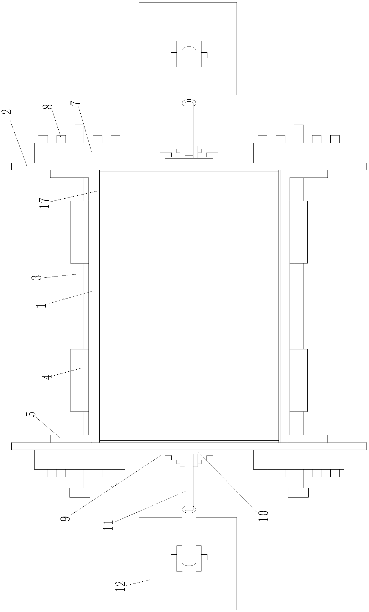
[0059] picture Figure 4-Figure 6 As shown, the difference between this embodiment and Embodiment 1 is that the outer formwork support assembly includes several parallel outer plate support rods 13 and several U-shaped buckles 14, and the two ends of the U-shaped opening of the U-shaped buckles 14 are connected to the outer formwork. The outer surface of 2 is fixedly welded, and the outer plate support rod 13 is sleeved in the U-shaped opening of the U-shaped buckle 14 and attached to the outer surface of the outer template 2 .

[0060] In the present application, the outer plate support bar 13 is fixed on the surface of the outer formwork 2 through the U-shaped buckle 14, and the outer plate support bar 13 forms an external support skeleton on the outer side of the outer formwork 2, which improves the strength of the outer formwork 2 and prevents the outside Formwork 2 deformed during pouring.

[0061] The two ends of the outer formwork 2 are respectively provided with a fix...


PUM


Abstract

The invention discloses an anti-deformation pouring mold for a building supporting column. The anti-deformation pouring mold comprises two parallel inner side templates (1) and two parallel outer sidetemplates (2), wherein a prismatic pouring space is formed by the two inner side templates (1) and the two outer side templates (2), the inner side templates (1) are arranged between the two outer side templates (2) and are perpendicular to the outer side templates (2), and the side edges of the inner side templates (1) are in contact with the outer side templates (2); and the outer side surfaceof each outer side template (2) is provided with an inner side template fixed supporting assembly, and each inner side template fixed supporting assembly penetrates through the outer side plate and isfixedly connected with the outer surface of the inner side template (1). The anti-deformation pouring mold provided by the invention has the advantages that the defects of the prior art can be overcome, and the structure design is reasonable and novel.

Description

technical field [0001] The invention relates to an anti-deformation pouring form for a building support column and a pouring construction method thereof, belonging to the field of construction. Background technique [0002] The scale of housing construction in our country is very huge. In recent years, 1.6 billion to 2 billion square meters of houses have been built every year. Such a huge construction scale is unprecedented in the world; in the history of our country, these decades are the peak period of housing construction. In the prior art, concrete pouring is generally used to construct the load-bearing column of the building. Concrete pouring refers to the process of pouring concrete into the mold until it is plasticized. In civil engineering, concrete and other materials are put into the mold to make a predetermined shape. Because the concrete cast-in-place building components have the characteristics of high strength, good durability, earthquake resistance and defo...

Claims


Application Information

Patent Timeline
Patent Type & Authority Applications(China)
IPC IPC(8): E04G13/02
CPCE04G13/02
Inventor 李翠翠马安东张杰
Owner 青建集团股份公司
Why Eureka
Try Eureka