Drawing die
A technology for drawing dies and die bases, which is used in forming tools, manufacturing tools, metal processing equipment, etc., can solve the problems of inconvenient unloading and low heat dissipation efficiency of stamping dies, and achieve convenient and fast unloading, improve work efficiency, Increase the effect of heat dissipation
- Summary
- Abstract
- Description
- Claims
- Application Information
AI Technical Summary
Problems solved by technology
Method used
Image
Examples
Embodiment 1
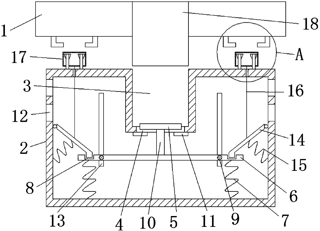
[0044] refer to figure 1 , a kind of stretching die, comprises upper mold base 1, punch 18, lower mold base 2, die 3, base 5, bearing plate 6, return spring one 7, two clamp rods 14, return spring two 15, two A pull cord 16 and two pull blocks 17.
[0045] Wherein, punch 18 is installed on the upper mold base 1 . The lower mold base 2 is a hollow structure. The concave mold 3 corresponding to the convex mold 18 is installed on the lower mold base 2, and the concave mold 3 and the lower mold base 2 are integrally formed to ensure the high quality of workpiece stretching. The workpiece is placed on the die 3, and then the punch 18 is used to drive the punch 18 to press the workpiece downward, thereby completing the work of stretching the workpiece. And the bottom of the die 3 is provided with a through hole 4, and the base 5 is located in the through hole 4; the base 5 and the through hole 4 have an interference fit. That is, the specification of the base 5 is consistent wit...
Embodiment 2
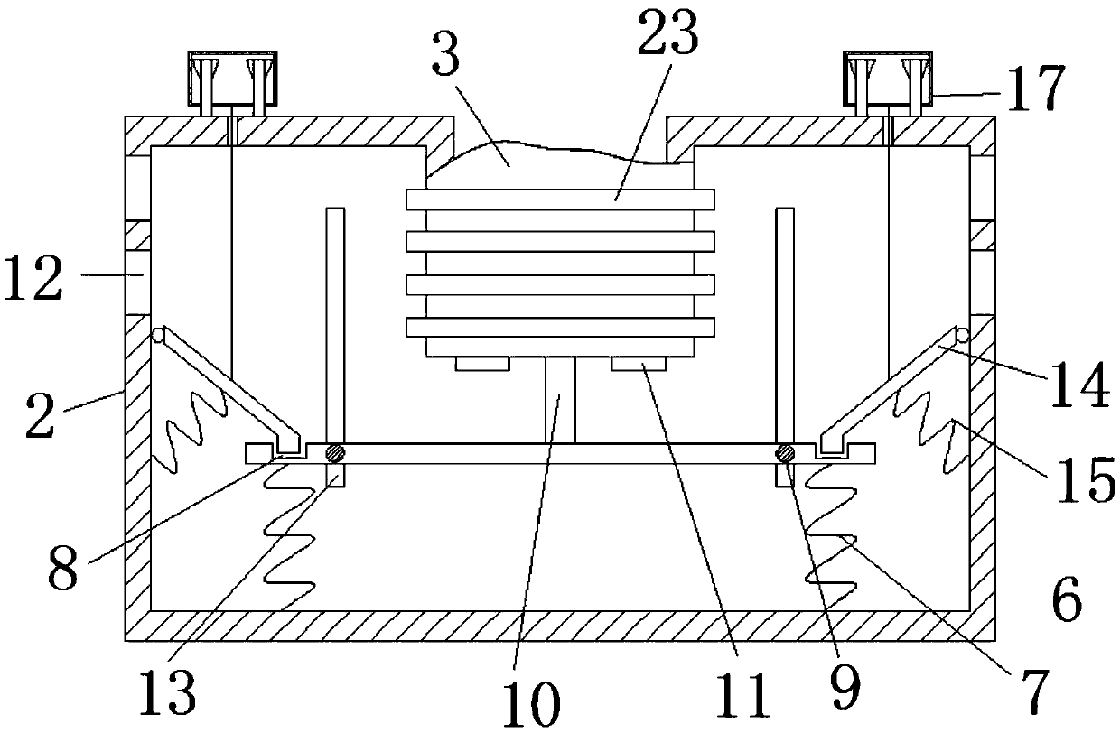
[0049] When utilizing the stretching die in embodiment 1 to stretch the workpiece, there is a huge friction force between the workpiece and the flange part of the die 3 . In this way, under the working conditions of continuous stamping, the performance of the drawing die will decrease, resulting in the frequent shutdown of the drawing die for maintenance in the later stage, which greatly reduces the production efficiency. For this reason, further improvement is made on the basis of the stretching die in Example 1. The specific improvements are as follows:
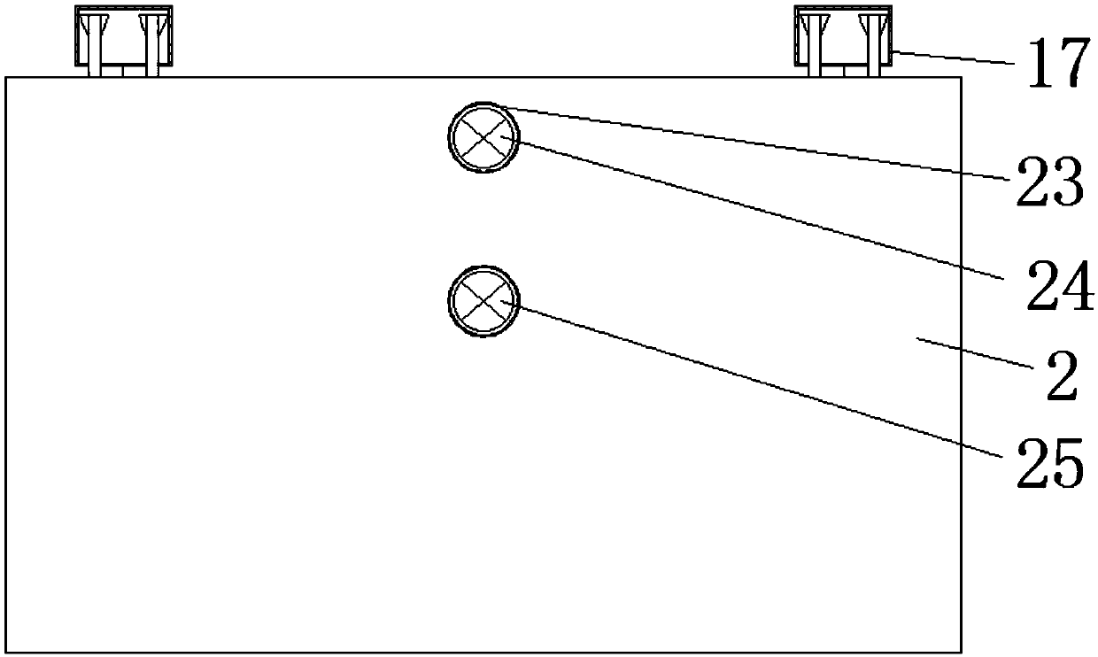
[0050] refer to Figure 2-3 The outer wall of the die 3 located inside the lower die base 2 is provided with a cooling structure, and the side wall of the lower die base 2 is provided with a plurality of cooling holes 12 . The effect of air crossing can be achieved by utilizing the cooling holes 12 . Increase air flow at die 3. The cooling structure includes a cooling water pipe 23 , a water inlet sealing plug 24 and a ...
Embodiment 3
[0054] In order to further improve the working efficiency of the stretching dies of Example 1 and Example 2, manual unloading was improved to automatic unloading. Specifically, as follows:
[0055] refer to figure 1 and Figure 4 , The drawing die also includes an automatic ejector reset mechanism. The ejector reset mechanism is arranged on the lower mold base 2 . The automatic ejector reset mechanism includes two pull blocks 17, four rubber clamping bars 19, two vertical bars 20 and four triangular blocks 22.
[0056] Wherein, the two pull blocks 17 are both hollow structures. The side walls of the two pull blocks 17 are symmetrically provided with two through holes 21 ; The two rubber snap rods 19 in each set of buckle mechanisms are mirror-symmetrical about the vertical centerline of the pull block 17 . The shortest linear distance between the two rubber clamps 19 in each group of buckle mechanisms is not greater than the length of the pull block 17, thereby ensuring ...
PUM
 Abstract
Description
Claims
Application Information
 - R&D
- Intellectual Property
- Life Sciences
- Materials
- Tech Scout
- Unparalleled Data Quality
- Higher Quality Content
- 60% Fewer Hallucinations
Browse by: Latest US Patents, China's latest patents, Technical Efficacy Thesaurus, Application Domain, Technology Topic, Popular Technical Reports.
© 2025 PatSnap. All rights reserved.Legal|Privacy policy|Modern Slavery Act Transparency Statement|Sitemap|About US| Contact US: help@patsnap.com


