Supercharge Your Innovation With Domain-Expert AI Agents!

Direct-drive permanent magnet rotor with holders

A permanent magnet rotor and cage technology, which is applied to the rotating parts of the magnetic circuit, magnetic circuit, magnetic circuit shape/style/structure, etc., can solve the problems of large gaps, limited length, and permanent magnets that cannot be attached to the body, and achieve an optimized magnetic field Structure, low processing cost and convenient processing

Pending Publication Date: 2019-04-23
横川机器人(深圳)有限公司
View PDF0 Cites 0 Cited by
  • Summary
  • Abstract
  • Description
  • Claims
  • Application Information

AI Technical Summary

Problems solved by technology

[0003] However, the above-mentioned direct drive motor rotor structure has the following disadvantages. Whether it is an inner rotor or an outer rotor, the length of the direct processing of the slots on the turntable is limited, which is only suitable for short permanent magnets, and the processing cost is high; if the slots are not processed directly To paste the permanent magnet, another limit cogging fixture is required for mounting. If there is no gap between the permanent magnets, it will cause the last permanent magnet to be stuck, or it is better to have a large and uneven gap after the permanent magnet is pasted, which will affect the performance of the motor. There is a gap between the magnets and the rotor is running. The permanent magnets with NS poles alternately mounted will loosen and attract together. The magnetic field distribution of the motor will be uneven, which will cause damage to the rotor.

Method used


Image

  • Direct-drive permanent magnet rotor with holders
  • Direct-drive permanent magnet rotor with holders
  • Direct-drive permanent magnet rotor with holders

Examples


Embodiment Construction

[0018] It should be understood that the specific embodiments described here are only used to explain the present invention, not to limit the present invention.

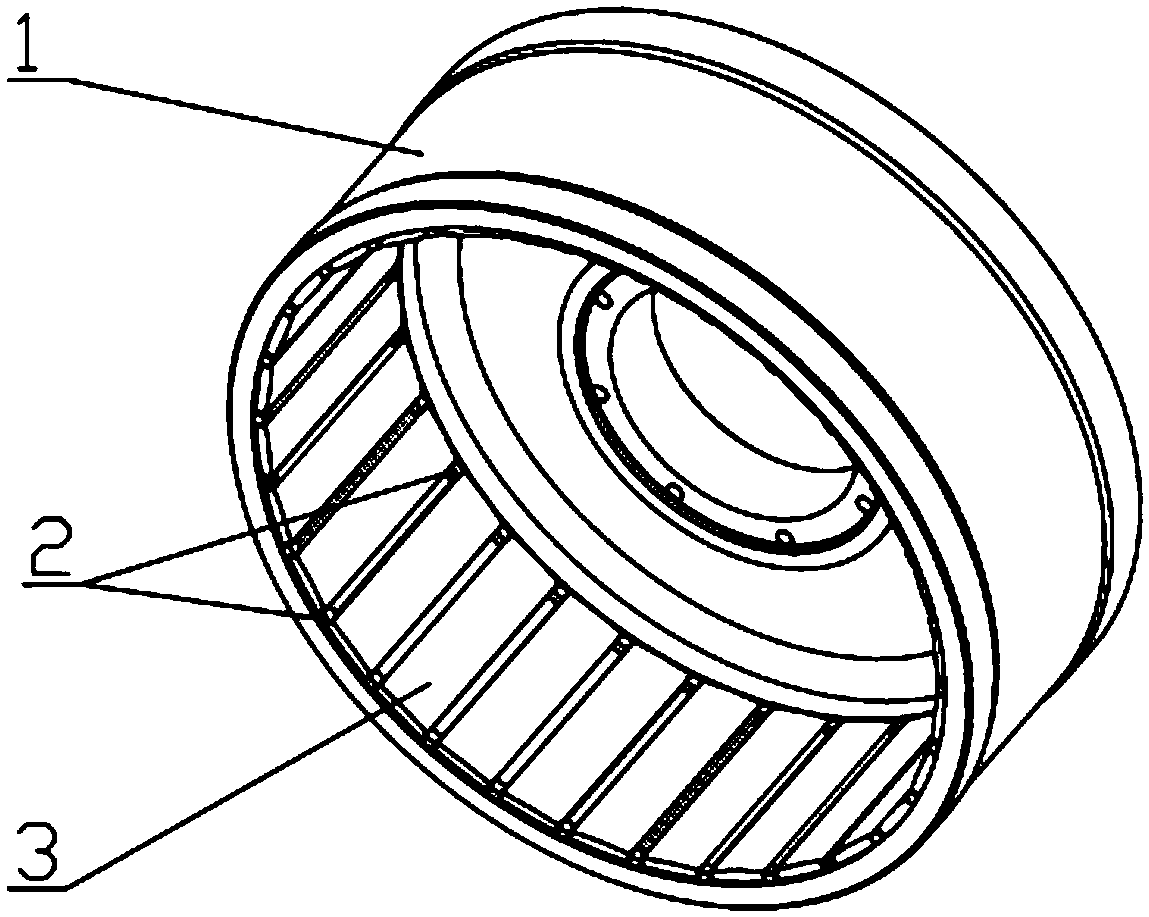
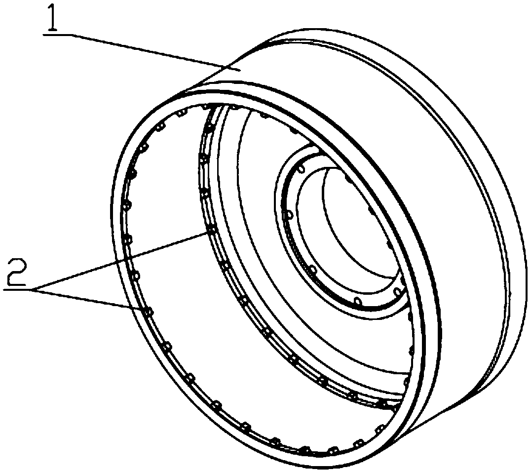
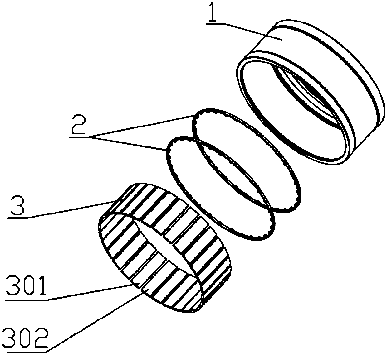
[0019] Considering the limited length of the current direct-drive motor rotor's turntable processing cogging, it is only suitable for short permanent magnets, and the processing cost is high. If the cogging is not processed, the last permanent magnet will not be attached, or it is better to post the last one. The gap is large and uneven, which affects the performance of the motor. In order to solve the above technical problems, the present invention proposes a direct-drive permanent magnet rotor with a cage.

[0020] The technical solution adopted in the present invention mainly includes a turntable, a bracket assembly, and a permanent magnet assembly. Wherein, there are slots at both ends of the surface of the turntable attached to the permanent magnet; the bracket assembly has a tooth groove, which can be a full cir...


PUM


Abstract

The invention discloses a direct-drive permanent magnet rotor with holders. The direct-drive permanent magnet rotor comprises a rotating disc, a support component and a permanent magnet component, wherein the support component comprises a first annular support and a second annular support, a first clamping groove for clamping the first support is formed in the upper end of the inner wall of the rotating disc, and a second clamping groove for clamping the second support is formed in the lower end of the inner wall of the rotating disc; a plurality of toothed grooves are evenly distributed in the inner wall of the first support and the second support; the permanent magnet component is arranged on the toothed grooves in a clamping manner. Compared with the prior art, the direct-drive permanent magnet rotor has the advantages that the direct-drive permanent magnet rotor is compact in structure, small in size, high in stability, low in processing cost and convenience in mounting; the holders are convenient to process, can be manufactured from plastic parts section by section and have high accuracy; the angle of the two holders are staggered to achieve inclined mounting of a permanent magnet, and accordingly, the structure of a magnetic field can be optimized.

Description

technical field [0001] The invention relates to the technical field of direct drive motor rotors, in particular to a direct drive permanent magnet rotor with a cage. Background technique [0002] The traditional direct drive motor rotor structure usually adopts the structure of directly processing the permanent magnets on the surface of the turntable or without the permanent magnets; [0003] However, the above-mentioned direct drive motor rotor structure has the following disadvantages. Whether it is an inner rotor or an outer rotor, the length of the direct processing of the slots on the turntable is limited, which is only suitable for short permanent magnets, and the processing cost is high; if the slots are not processed directly To paste the permanent magnet, another limit cogging fixture is required for mounting. If there is no gap between the permanent magnets, it will cause the last permanent magnet to be stuck, or it is better to have a large and uneven gap after th...

Claims


Application Information

Patent Timeline
IPC IPC(8): H02K1/30H02K1/27
CPCH02K1/2753H02K1/30
Inventor 王建云王书华刘步军
Owner 横川机器人(深圳)有限公司
Features
  • R&D
  • Intellectual Property
  • Life Sciences
  • Materials
  • Tech Scout
  • Unparalleled Data Quality
  • Higher Quality Content
  • 60% Fewer Hallucinations
Learn More