Oily sludge treatment method

A treatment method and sludge technology, which are applied in the pyrolysis treatment of sludge, petroleum industry, special forms of dry distillation, etc., can solve the problems of low pyrolysis efficiency, uneven heating and pyrolysis of materials, etc. The effect of heating up the pyrolysis uniformity and reducing the oxygen content of the material

Active Publication Date: 2019-04-23
航天国环技术集团有限公司
View PDF17 Cites 2 Cited by
  • Summary
  • Abstract
  • Description
  • Claims
  • Application Information

AI Technical Summary

Problems solved by technology

[0005] Therefore, the technical problem to be solved in the embodiment of the present invention is that the oily sludge treatment method in the prior art has uneven pyrolysis and low pyrolysis efficiency when the material is heated up in the microwave cracking furnace.

Method used


Image

  • Oily sludge treatment method
  • Oily sludge treatment method
  • Oily sludge treatment method

Examples


Embodiment 1

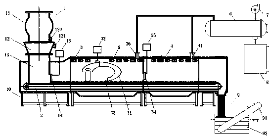
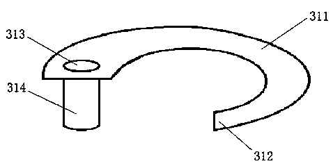
[0043] This embodiment provides a treatment system for oily sludge, which is mainly applied to the harmless and resourceful treatment of oily sludge generated in the petroleum exploitation, refining and petrochemical industries, such as figure 1 As shown, the processing system includes: a feeding device 1, a feeding bin 11, a feeding deoxidizing bin 12, an air inlet 121, an air outlet 122, a feeding bin 13, a feeding bin door 14, a first pushing device 15, Horizontal conveying device 2, main microwave pyrolysis furnace 3, screw conveying device 31, second pushing device 32, temperature detection device 33, main furnace door 34, third pushing device 35, first exhaust port 36, auxiliary microwave pyrolysis device Furnace 4, second exhaust port 41, microwave port 5, condensing device 6, air extraction device 7, oil-water separation device 8, discharging device 9, slag extractor 91, pool 92, rack 10. The feeding bin door 14 , the horizontal conveying device 2 , the main microwave ...

Embodiment 2

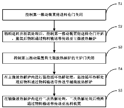
[0059] This embodiment provides a treatment method for oily sludge, which can be applied to the treatment system for oily sludge in Embodiment 1. The treatment method includes the following steps:

[0060] S1, control the first pushing device 15 to close the feeding bin door 14;

[0061] S2. After the material is fed and deoxidized, the first pushing device 15 is controlled to open the feeding bin door 14, and the deoxidized material is transported to the main microwave pyrolysis furnace 3 through the material conveyor belt;

[0062] S3, control the third pushing device 35 to close the main furnace door 34 of the main microwave pyrolysis furnace 3;

[0063] S4, temperature-controlled cyclic pyrolysis treatment is performed in the main microwave pyrolysis furnace 3, and the material after the temperature-controlled cyclic pyrolysis treatment is transported to the auxiliary microwave pyrolysis furnace 4 through the material conveyor belt;

[0064] S5 , performing secondary pyro...


PUM


Abstract

The invention discloses an oily sludge treatment method, and relates to the technical field of garbage treatment. The treatment method includes the steps: controlling a first push device to close a feed bin gate; feeding and deoxidizing materials, controlling the first push device to open the feed bin gate, and conveying the deoxidized materials to a main microwave pyrolysis furnace by a materialconveying belt; controlling a third push device to close a main furnace door of the main microwave pyrolysis furnace; performing temperature control cycling pyrolysis treatment in the main microwave pyrolysis furnace, and conveying the materials after temperature control cycling pyrolysis treatment to an auxiliary microwave pyrolysis furnace by the material conveying belt; performing secondary pyrolysis treatment in the auxiliary microwave pyrolysis furnace, and conveying residues after secondary pyrolysis treatment to a discharging device by the material conveying belt. The oily sludge treatment method has the advantages that the materials in the microwave pyrolysis furnaces are uniformly heated and pyrolyzed, and pyrolysis efficiency is high.

Description

technical field [0001] The invention relates to the technical field of garbage disposal, in particular to a method for treating oily sludge. Background technique [0002] Oily sludge mainly comes from oil exploration, refining and petrochemical industries. With the increase of oil production, the total amount of oily sludge produced is also increasing, and the pollution to the environment is becoming more and more serious. Therefore, whether it is from the perspective of environmental protection, maintenance of normal production or from the perspective of energy recovery, it is necessary to carry out harmless and resourceful treatment of oily sludge. [0003] At present, the harmless treatment of oily sludge is mainly: oily sludge is heated by microwave under anaerobic conditions and treated by thermal cracking technology, thereby improving the recovery rate of oil and gas resources in oily sludge, reducing environmental pollution and improving economic benefits. . [0004...

Claims


Application Information

Patent Timeline
Patent Type & Authority Applications(China)
IPC IPC(8): C02F11/10C10B53/00
CPCC02F11/10C10B53/00Y02W10/40
Inventor 吴雅菲范博葛超逸
Owner 航天国环技术集团有限公司
Why Eureka
Try Eureka