
Punching machine die for hydraulic pipe bending machine bending pipes efficiently

A pipe bending machine and pipe bending technology, which is applied in the field of punch press moulds for hydraulic pipe benders, can solve problems such as the inability to meet the needs of the peak season of fitness equipment production, the inability of punch press moulds to quickly locate and punch, and the reduction of pipe bending efficiency of hydraulic pipe benders. , to achieve the effect of simple structure, reasonable design and convenient disassembly and assembly

Inactive Publication Date: 2019-04-23
TIANJIN AOLIN
View PDF0 Cites 0 Cited by
  • Summary
  • Abstract
  • Description
  • Claims
  • Application Information

AI Technical Summary

Problems solved by technology

In the processing and manufacturing of fitness equipment, the hydraulic pipe bender is one of the indispensable processing equipment. The hydraulic pipe bender has the pipe bending function and the pipe bending tool with the jacking function. The punch die is an important die of the hydraulic pipe bender. However, the structure design of the currently used punching die is unreasonable, the punching die cannot be quickly positioned for punching, and the workpiece needs to be frequently adjusted for punching, which greatly reduces the bending efficiency of the hydraulic pipe bending machine and cannot meet the needs of fitness equipment in the peak production season

Method used


Image

  • Punching machine die for hydraulic pipe bending machine bending pipes efficiently
  • Punching machine die for hydraulic pipe bending machine bending pipes efficiently

Examples


Embodiment Construction

[0013] Below in conjunction with accompanying drawing and embodiment the present invention will be further described:

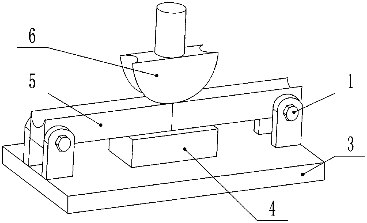
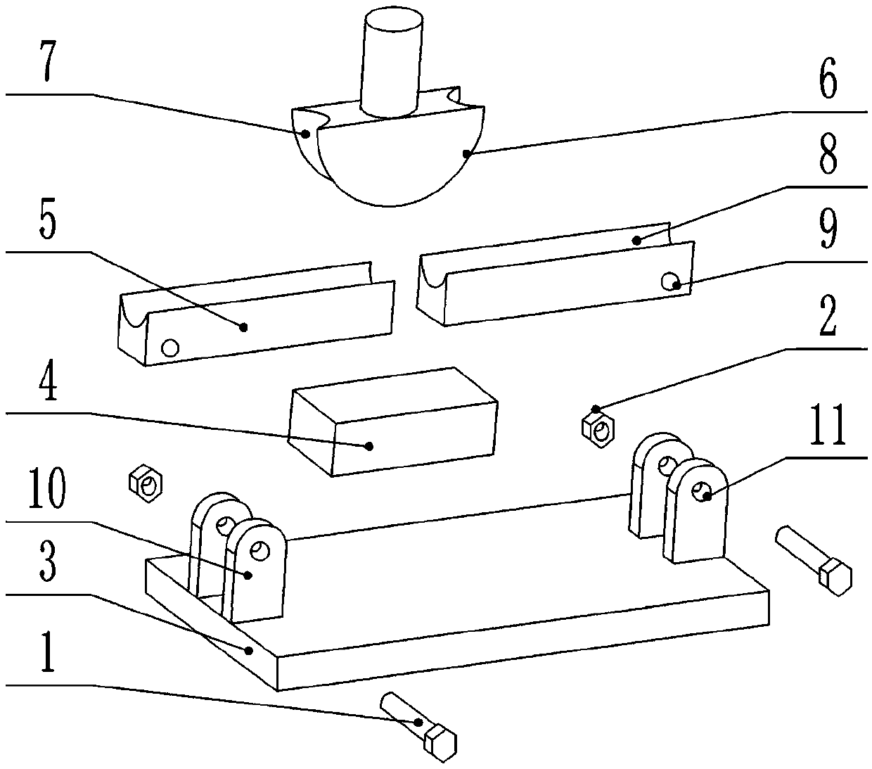
[0014] As shown in the figure, a high-efficiency hydraulic pipe bender punch die for pipe bending includes a lower die 5 and an upper die 6, and is characterized in that the lower die 5 is located below the upper die 6, and the upper die The cross section of 6 is set in the shape of a half-bent pipe wheel, and the curved surface of the upper die 6 is provided with a pipe bend groove 7, and the center of the horizontal plane of the upper die 6 is vertically fixed with a connecting rod, and the lower die 5 includes the elbow lower die clamping block one and the elbow lower die clamping block two, the elbow lower die clamping block one and the elbow lower die clamping block two are arranged flush from left to right, the elbow lower die clamping block two The upper part of the mold clamping block 1 and the elbow lower mold clamping block 2 are coaxially provided ...


PUM


Abstract

The invention provides a punching machine die for a hydraulic pipe bending machine bending pipes efficiently. The punching machine die comprises a lower die body and an upper die body. The punching machine die is characterized in that the lower die body is located below the upper die body, a first pipe bending lower die clamping block and a second pipe bending lower die clamping block are detachably installed on an installing plate through bolts, a buffering cushion block is arranged under the contact end of the first pipe bending lower die clamping block and the second pipe bending lower dieclamping block, and the buffering cushion block is located on the upper surface of a die installing base. The punching machine die is simple in structure, reasonable in design and convenient to assemble and disassemble, by arranging the lower die body comprising the first pipe bending lower die clamping block and the second pipe bending lower die clamping block, a guide groove, the upper die bodyprovided with a first pipe bending groove, the buffering cushion block and the die installing base, a workpiece to be punched is located on the punching machine die rapidly, frequent adjusting is notneeded for punching and machining the workpiece, the pipe bending efficiency of the hydraulic pipe bending machine is improved greatly, and the requirement for fitness equipment during the productionpeak season is met.

Description

technical field [0001] The invention relates to the technical field of dies for hydraulic pipe benders, in particular to a punch die for hydraulic pipe benders with high pipe bending efficiency. Background technique [0002] With the improvement and improvement of people's living material level, people are more and more aware of the importance of fitness. In order to meet the needs of indoor exercise and fitness, various fitness exercises are flourishing, and various sports and fitness equipment have emerged as the times require. In the processing and manufacturing of fitness equipment, the hydraulic pipe bender is one of the indispensable processing equipment. The hydraulic pipe bender has the pipe bending function and the pipe bending tool with the jacking function. The punch die is an important die of the hydraulic pipe bender. However, the structure design of the currently used punching die is unreasonable, the punching die cannot be quickly positioned for punching, and ...

Claims


Application Information

Patent Timeline
Patent Type & Authority Applications(China)
IPC IPC(8): B21D7/06
CPCB21D7/06
Inventor 张江杨振书高爱东
Owner TIANJIN AOLIN
Learn More