
Testing method based on landing movement foot area and shoe sole finite element modeling

A testing method, finite element technology, applied to foot or shoe last measuring devices, footwear, clothing, etc., can solve problems such as increased cost, non-conformity, and increased risk of injury to subjects, so as to save costs and avoid rough surface effect

Inactive Publication Date: 2019-04-23
SHANGHAI UNIV OF ENG SCI
View PDF5 Cites 8 Cited by
  • Summary
  • Abstract
  • Description
  • Claims
  • Application Information

AI Technical Summary

Problems solved by technology

[0007] From the point of view of the motion state, the traditional impact test cannot truly simulate the actual motion state. Although the finite element simulation is better in establishing the geometric model of the foot and sports shoes, they are all static simulations and do not conform to actual situation
[0008] From the perspective of cost, compared with the motion simulation on finite element software, using real people to conduct shoe sole shock absorption experiments will undoubtedly increase the cost, and also increase the risk of injury to the subjects

Method used


Image

  • Testing method based on landing movement foot area and shoe sole finite element modeling
  • Testing method based on landing movement foot area and shoe sole finite element modeling
  • Testing method based on landing movement foot area and shoe sole finite element modeling

Examples


Embodiment Construction

[0054] The present invention will be described in detail below in conjunction with the accompanying drawings and specific embodiments. This embodiment is carried out on the premise of the technical solution of the present invention, and detailed implementation and specific operation process are given, but the protection scope of the present invention is not limited to the following embodiments.

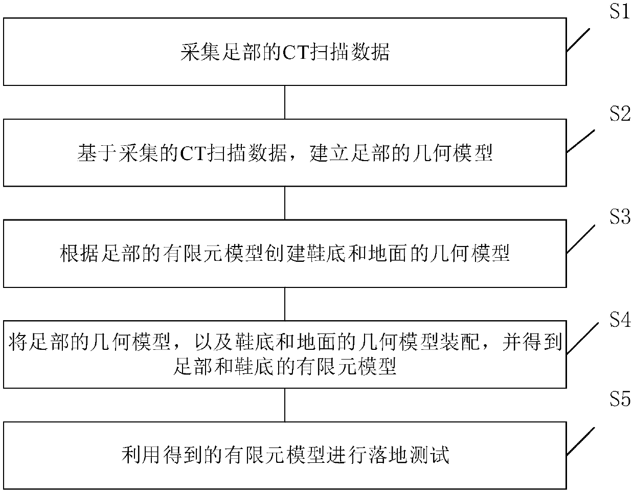
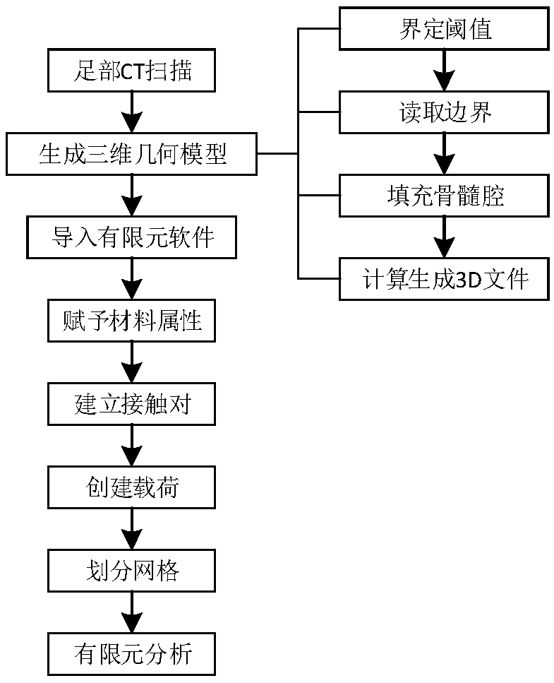
[0055] A test method for finite element modeling of the foot and sole based on landing motion, such as figure 1 with figure 2 shown, including:

[0056] Step S1: collecting CT scan data of the foot;

[0057] Step S2: Based on the collected CT scan data, establish a geometric model of the foot, specifically including:

[0058]Step S21: Import the CT scan data of the foot. In this embodiment, the CT scan data of the left foot (the CT scan data of the left foot of a healthy volunteer is used), that is, the DICM file is imported into the medical reverse engineering processing software...


PUM


Abstract

The invention relates to a testing method based on landing movement foot area and shoe sole finite element modeling. The method comprises the steps that S1, CT scanning data of a foot area is collected; S2, a foot area geometric model is established based on the collected CT scanning data; S3, geometric models of a shoe sole and ground are established according to a foot area finite element model;S4, the foot area geometric model, the shoe sole geometric model and the ground geometric model are assembled to obtain foot area and shoe sole finite element models; S5, landing testing is conductedon the obtained finite element models. Compared with the prior art, the shock-absorbing performance of the shoe sole in the model can be conducted, shoe sole materials and structures can be changed at will, shoe sole and foot area force bearing situations are predicted to guide the designing and production of sneakers, and a large amount of cost is reduced compared with a traditional manner in which a real object is made and then tested after being put on a body.

Description

technical field [0001] The invention relates to the field of testing the shock-absorbing performance of sports shoe soles, in particular to a testing method based on finite element modeling of feet and soles based on landing motion. Background technique [0002] Among all the sports equipment, the relationship between shoes and sports is the closest, the most direct and the most common. The core technology of sports shoes is mainly reflected in the sole technology. The early biomechanical research focused on the shape and structure of the foot, followed by the measurement and analysis of kinematics and dynamics. Today, it is the application of high technology and new materials. All rely on advances in biomechanical measurement and analysis techniques. One of the main functions of the sole is exactly shock absorption, and the main purpose of shock absorption is to reduce the impact to reduce the damage of the foot. The shock absorption of sports shoes soles is divided into ...

Claims


Application Information

Patent Timeline
Patent Type & Authority Applications(China)
IPC IPC(8): A43D1/08
CPCA43D1/08
Inventor 柯思成谢红李杰聪谢月婵随建美姚好
Owner SHANGHAI UNIV OF ENG SCI
Learn More