
Method and system for correcting brightness of LED box bodies

A technology of LED cabinet and calibration method, which is applied in the direction of instruments, static indicators, etc., can solve problems such as brightness and chromaticity information environment error, cabinet brightness and color difference, exposure difference, etc., to achieve uniformity, ensure consistency, and eliminate bright colors The effect of degree difference

Active Publication Date: 2019-04-19
SHENZHEN LIDING PHOTOELECTRIC TECH
View PDF17 Cites 3 Cited by
  • Summary
  • Abstract
  • Description
  • Claims
  • Application Information

AI Technical Summary

Problems solved by technology

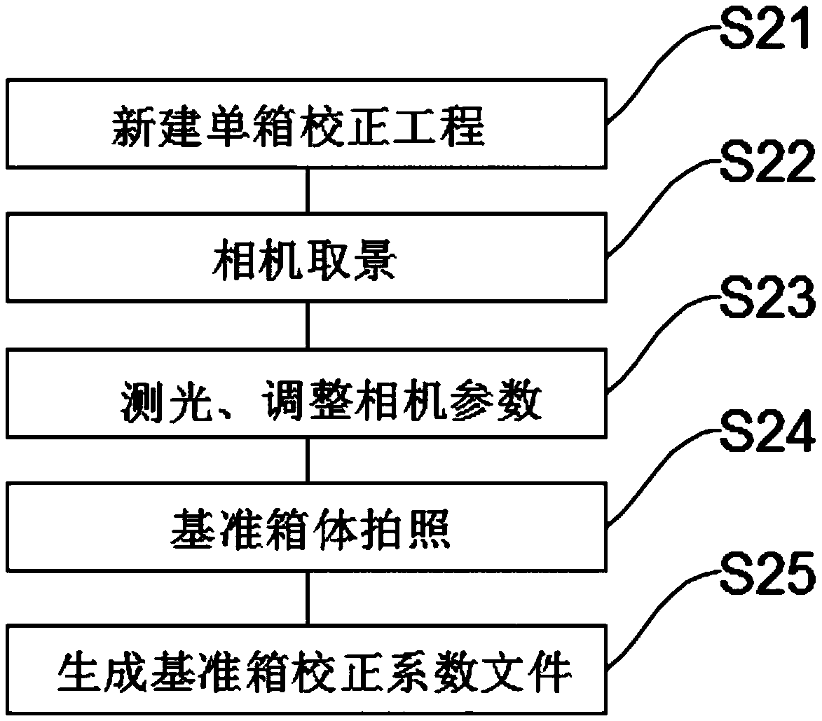
[0003] There is a common situation in the LED display industry that multiple batches of cabinets with bright color differences are mixed. The current single-box calibration can only solve the problem of bright color difference inside the cabinet, and the difference in bright colors between cabinets cannot be solved; for example: the application number is 201410292607.1, Chinese invention patents titled LED Display Brightness and Chromaticity Correction Method and LED Cabinet Brightness and Chromaticity Correction Method;
[0004] The single-box correction in the prior art, no matter whether it uses an industrial camera or a SLR camera to collect brightness and chromaticity information, the collection accuracy cannot meet the production requirements, and a third-party device is required to calibrate the accuracy of the camera data, or a calibration light source is used to calibrate the camera. However, this method When performing a single cabinet calibration, there is still an exposure difference for each photo, resulting in environmental errors in the brightness and chromaticity information between the LED cabinets collected each time; for example: the application number is 201610077983.8, and the name is LED Display Module Uniformity Calibration Method in China Patent

Method used


Image

  • Method and system for correcting brightness of LED box bodies
  • Method and system for correcting brightness of LED box bodies
  • Method and system for correcting brightness of LED box bodies

Examples


Embodiment Construction

[0040] The technical solutions in the embodiments of the present invention will be clearly and completely described below in conjunction with the drawings in the present invention. Apparently, the described embodiments are only some of the embodiments of the present invention, not all of them. Based on the embodiments of the present invention, all other embodiments obtained by persons of ordinary skill in the art without making creative efforts belong to the protection scope of the present invention.

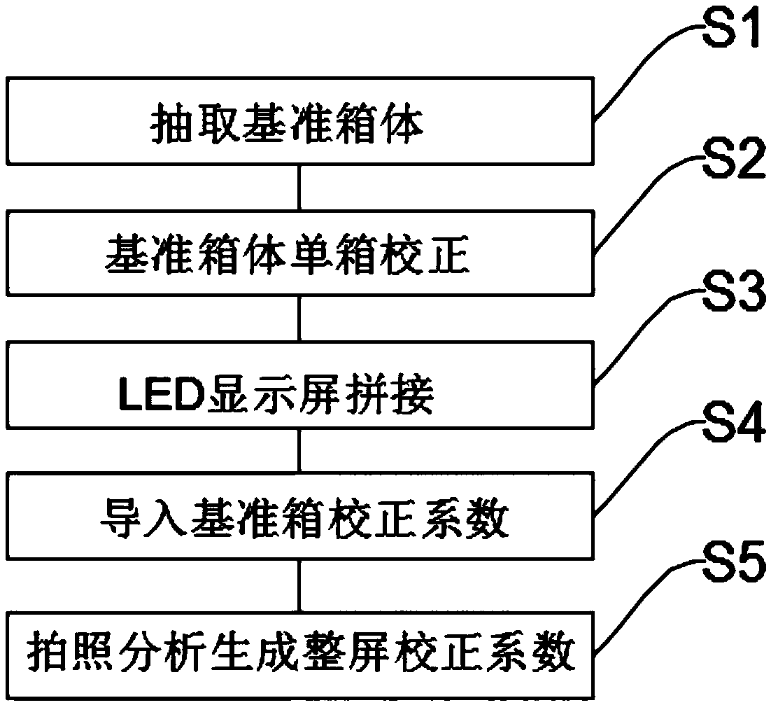
[0041] like figure 1 As shown, a method for correcting brightness and chromaticity of an LED cabinet according to an embodiment of the present invention includes the following steps:

[0042]Step S1: Among the LED cabinets, one or more LED cabinets are selected as calibration reference cabinets, and the remaining LED cabinets are calibration cabinets. Specifically, select one or more LED cabinets in the same batch of LED cabinets as the calibration reference cabinet, and the re...


PUM


Abstract

The invention relates to the technical field of brightness correction of LED box bodies, in particular to a method and system for correcting brightness of LED box bodies. The method for correcting brightness of LED box bodies provided by the invention comprises the following steps: (1) extracting a reference box body, (2) correcting the single box of the reference box body, (3) splicing a LED display screen, (4) introducing a correction coefficient of the reference box, and (5) performing photograph analysis to generate a full-screen correction coefficient. The method for correcting brightnessof LED box bodies provided by the invention selects a reference box body as a reference, and then analyzes and generates a full-screen correction factor file corresponding to the corrected box body according to the introduced correction coefficient file of the reference box, which eliminates the difference in brightness between any batch of LED box bodies, and enables mixing between any batch ofLED box bodies. The system for correcting brightness of LED box bodies provided by the invention comprises a reference box body, a corrected box body, a brightness collecting terminal and a control processing terminal, which realizes brightness correction between the LED box bodies.

Description

technical field [0001] The invention relates to the technical field of brightness and chromaticity correction of LED cabinets, in particular to a method and system for correcting brightness and chromaticity of LED cabinets. Background technique [0002] Due to the discreteness and attenuation of LED light-emitting tubes and the discreteness of circuit components, LED displays have inconsistent brightness and chromaticity, which will seriously affect the display quality. In order to overcome the problem of non-uniformity of brightness and chromaticity of LED display screen, point-by-point correction technology came into being and developed rapidly, which can significantly improve the uniformity of LED display screen and improve the display quality. According to the different application occasions, the existing calibration technology can be roughly divided into two types: one is box-by-box calibration on the production line, that is, box calibration; the other is on-site large...

Claims


Application Information

Patent Timeline
IPC IPC(8): G09G3/32
CPCG09G3/32
Inventor 何志民宁一铮
Owner SHENZHEN LIDING PHOTOELECTRIC TECH
Learn More