Image processing method, device, electronic device and computer storage medium
A technology for image processing and images to be detected, which is applied in the field of image processing and can solve problems such as poor accuracy
- Summary
- Abstract
- Description
- Claims
- Application Information
AI Technical Summary
Problems solved by technology
Method used
Image

Examples
Embodiment 1
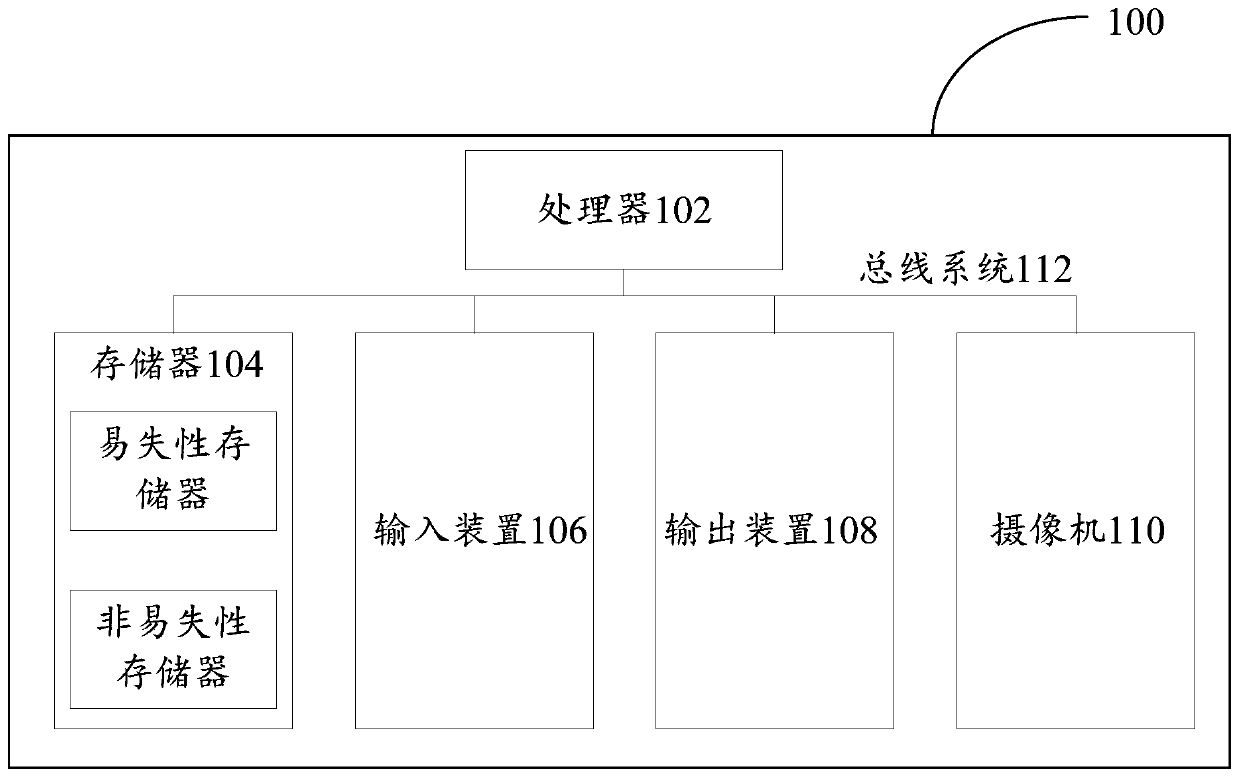
[0041] First, refer to figure 1 The electronic device 100 for implementing the embodiments of the present invention will be described, and the electronic device can be used to run the image processing methods of the various embodiments of the present invention.
[0042] Such as figure 1 As shown, the electronic device 100 includes one or more processors 102, one or more memories 104, an input device 106, an output device 108, and a camera 110. These components are connected via a bus system 112 and / or other forms of connection mechanisms (not shown). out) interconnection. It should be noted that figure 1 The components and structure of the electronic device 100 shown are only exemplary, not limiting, and the electronic device may also have other components and structures as required.
[0043] The processor 102 may be implemented in at least one hardware form of a digital signal processor (DSP), a field programmable gate array (FPGA), a programmable logic array (PLA) and an ...
Embodiment 2
[0050] According to an embodiment of the present invention, an embodiment of an image processing method is provided. It should be noted that the steps shown in the flow charts of the drawings can be executed in a computer system such as a set of computer-executable instructions, and, Although a logical order is shown in the flowcharts, in some cases the steps shown or described may be performed in an order different from that shown or described herein.
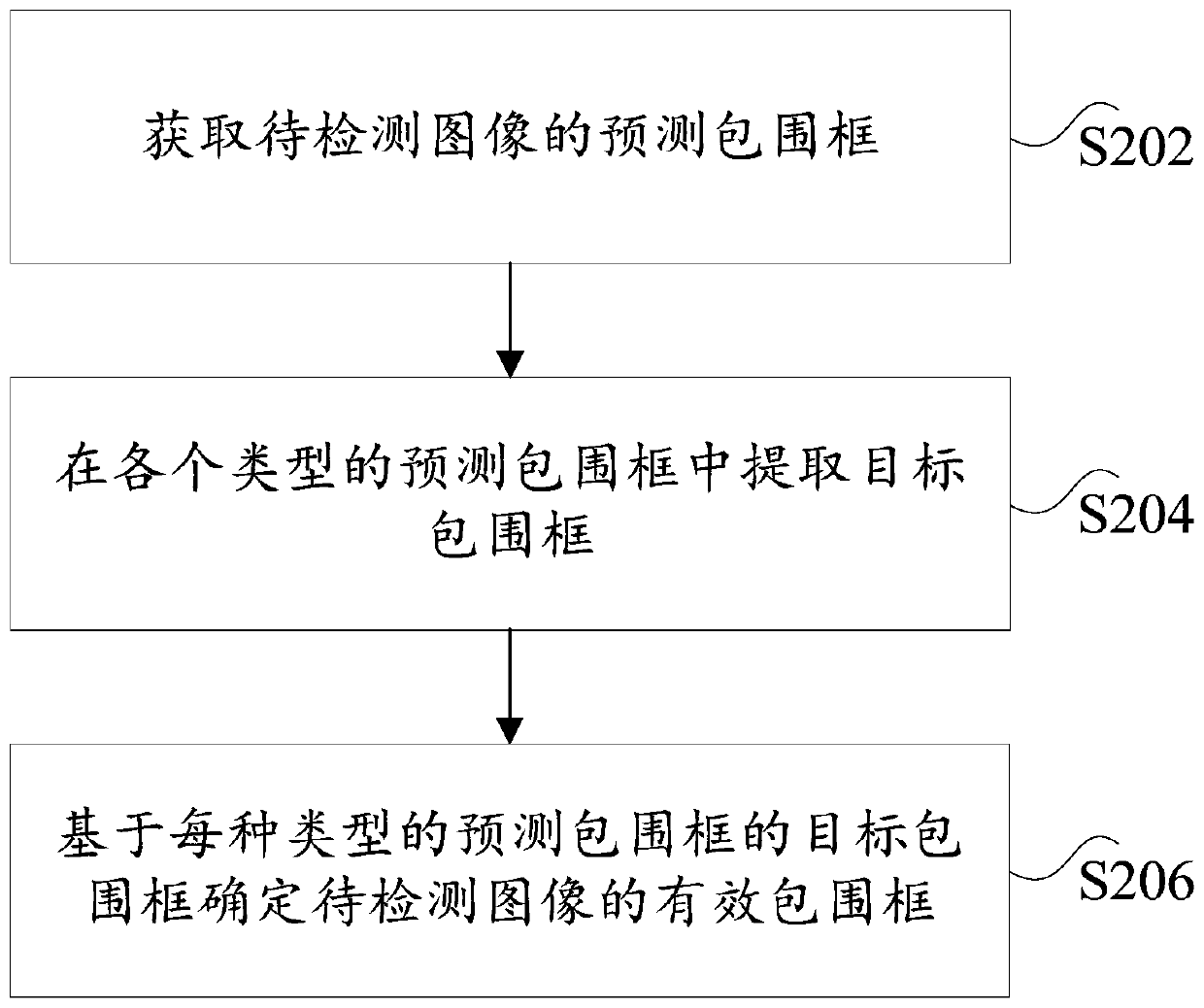
[0051] figure 2 is a flowchart of an image processing method according to an embodiment of the present invention, such as figure 2 As shown, the method includes the following steps:
[0052] Step S202, obtaining the predicted bounding box of the image to be detected, the predicted bounding box includes multiple types of predicted bounding boxes, and the type of the predicted bounding box is determined according to the overlap rate of the predicted bounding box;
[0053] In the embodiment of the present invention, the image...
Embodiment 3
[0160] The embodiment of the present invention also provides an image processing device, the image processing device is mainly used to execute the image processing method provided in the above content of the embodiment of the present invention, the image processing device provided by the embodiment of the present invention will be described in detail below introduce.
[0161] Figure 13 is a schematic diagram of an image processing device according to an embodiment of the present invention, such as Figure 13 As shown, the image processing device mainly includes an acquisition unit 10, an extraction unit 20 and a determination unit 30, wherein:
[0162] An acquisition unit, configured to acquire a predicted bounding box of the image to be detected, the predicted bounding box includes multiple types of predicted bounding boxes, and the type of the predicted bounding box is determined according to the overlap rate of the predicted bounding box;
[0163] An extraction unit, con...
PUM
 Abstract
Description
Claims
Application Information
 - Generate Ideas
- Intellectual Property
- Life Sciences
- Materials
- Tech Scout
- Unparalleled Data Quality
- Higher Quality Content
- 60% Fewer Hallucinations
Browse by: Latest US Patents, China's latest patents, Technical Efficacy Thesaurus, Application Domain, Technology Topic, Popular Technical Reports.
© 2025 PatSnap. All rights reserved.Legal|Privacy policy|Modern Slavery Act Transparency Statement|Sitemap|About US| Contact US: help@patsnap.com