
Single-pair supersonic flow direction vortex generation device

A generation device, supersonic technology, applied in the direction of internal combustion engine testing, etc., to achieve uniform flow parameters, easy flow field display, and avoid pollution.

Active Publication Date: 2019-04-19
NANJING UNIV OF AERONAUTICS & ASTRONAUTICS
View PDF6 Cites 5 Cited by
  • Summary
  • Abstract
  • Description
  • Claims
  • Application Information

AI Technical Summary

Problems solved by technology

Finally, the above two flow direction vortex generation methods will directly restrict the effective test range of the direct connection test bench because they both need to occupy a certain flow channel area.

Method used


Image

  • Single-pair supersonic flow direction vortex generation device
  • Single-pair supersonic flow direction vortex generation device
  • Single-pair supersonic flow direction vortex generation device

Examples


Embodiment Construction

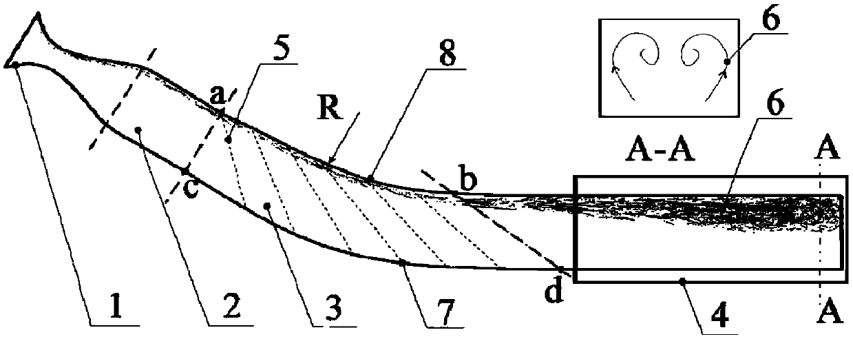
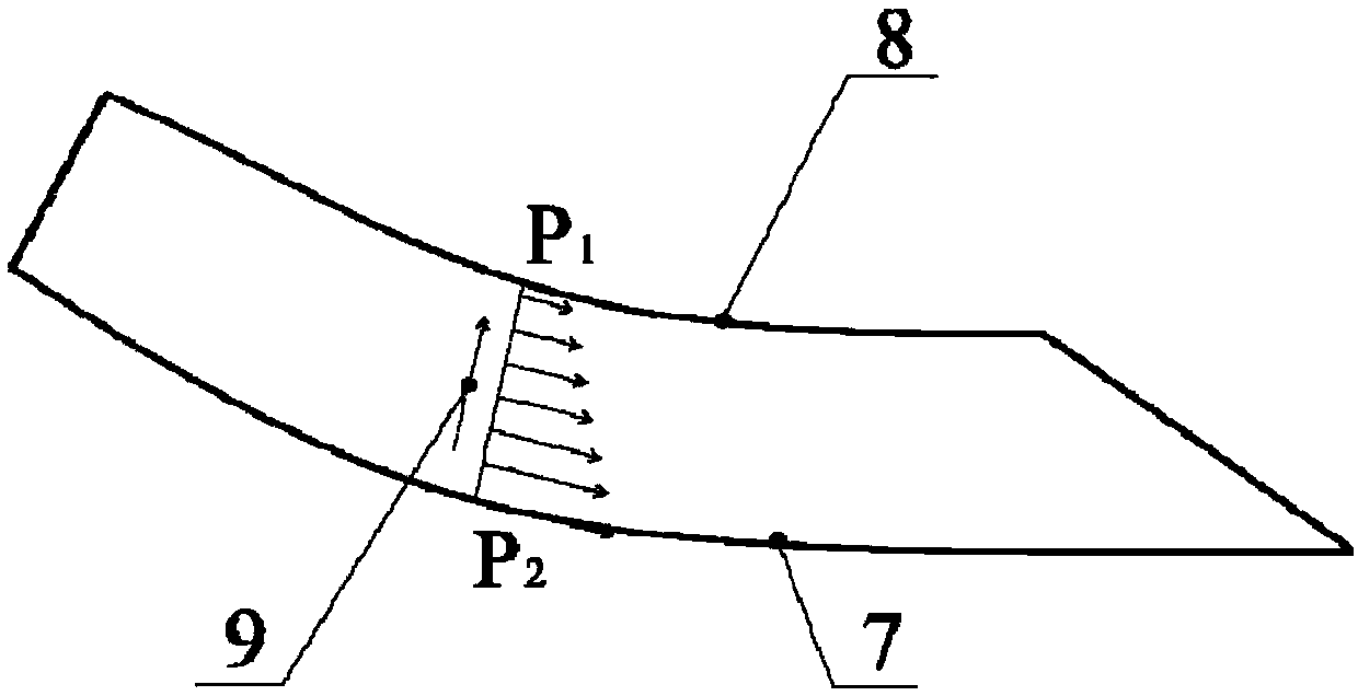
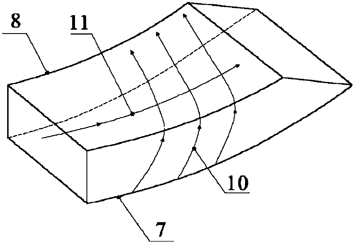
[0015] see figure 1 As shown, the present invention provides a single-pair supersonic flow direction vortex generating device without background wave system, including a Laval nozzle 1 , a transition section 2 , a vortex generating section 3 and a test window 4 . The vortex generating section 3 is a curved pipe, the upper wall profile 8 of the vortex generating section 3 is a circular arc with a radius R, and the lower wall 7 of the vortex generating section 3 is a curved profile. The local tangential direction of the starting point a of the upper wall surface is consistent with the tangential direction of the starting point of the lower wall surface 7, and the tangential direction of the ending point b of the upper wall surface is consistent with the tangential direction of the ending point of the lower wall surface 7. Inside the vortex generating section 3, there are a series of continuous right-going expansion waves 5 formed from the upper wall of the pipeline. The first no...


PUM


Abstract

The invention discloses a single-pair supersonic flow direction vortex generation device. The device comprises a laval nozzle, a transition section, a vortex generation section and a test window whichare sequentially connected. A uniform supersonic flow is formed through the laval nozzle and the transition section and enters the vortex generation section, the side wall boundary layer is induced to form transverse flow by means of radial pressure gradient, a pair of large-scale flow direction vortices are generated on one side of a pipeline, and through the design of wave elimination, a uniform and background-free supersonic core flow and a fully-developed single-pair supersonic flow vortex can be generated in the test window. The vortex generation device has the advantages of being simplein structure, convenient to integrate with an existing test bed and display a flow field, and effectively avoiding the pollution of a background wave system to the flow field. In addition, the flow channel area of a test device is gradually increased, and an additional vortex generation device is not needed, so that the requirement of a direct-connected test bed on the plugging degree of a modelis more easily met, a feasible test device is provided for researching the interference mechanism of a shock wave string and the supersonic flow direction vortices in a scramjet engine.

Description

technical field [0001] The invention relates to the field of scramjet aerodynamic experiments, in particular to a supersonic vortex generating device. Background technique [0002] The supersonic flow direction vortex is a flow phenomenon that widely exists in scramjet engines, such as binary inlet / isolation section, revolving inlet / isolation section and side pressure inlet / isolation section. The scale of the above-mentioned flow vortex is generally very large, which can basically reach about 40% to 50% of the entire pipeline cross section, and is the main flow feature in the inlet / isolation section. The existence of the supersonic flow direction vortex will bring many adverse effects on the performance of the engine: firstly, it will enhance the mixing of airflow and increase the total pressure loss, thereby affecting the effective thrust of the engine; The degree of distortion, the accumulation of low total pressure fluid is formed locally, and this part of low energy flu...

Claims


Application Information

Patent Timeline
Patent Type & Authority Applications(China)
IPC IPC(8): G01M15/04
CPCG01M15/04
Inventor 黄河峡张可心林正康郭赟杰谭慧俊鲁世杰马志明
Owner NANJING UNIV OF AERONAUTICS & ASTRONAUTICS
Learn More