A concrete conveying device

A technology for conveying devices and transport pipes, which is applied in construction, infrastructure engineering, etc., and can solve problems such as discontinuous pouring, difficulty in controlling excess irrigation, and long time

Active Publication Date: 2020-11-27
SHANGHAI MARITIME UNIVERSITY
View PDF6 Cites 0 Cited by
  • Summary
  • Abstract
  • Description
  • Claims
  • Application Information

AI Technical Summary

Problems solved by technology

[0003] In the existing concrete pouring process, due to the casing drilling process, the position of the drilled hole is about 1.5-2 meters above the ground, so that the concrete pouring cannot be done in a self-unloading manner, and the pouring method of lifting materials with a large bucket is often used method, this kind of pouring method, in the process of on-site pouring, taking 10 cubic meters of concrete as an example, according to statistics, the pouring time is usually about 30-40 minutes, so the pouring method of using a large bucket to lift materials has the disadvantage of discontinuous pouring and long time , overfilling is difficult to control, and the amount of concrete waste is large, which will bring uncertain risk factors to the quality of piles in the later stage

Method used


Image

  • A concrete conveying device
  • A concrete conveying device
  • A concrete conveying device

Examples


Embodiment Construction

[0043] based on the following Figure 1 to Figure 8 , specifically explain the preferred embodiment of the present invention.

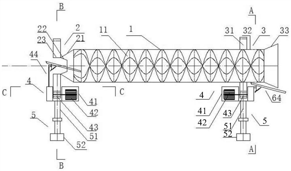
[0044] The invention provides a concrete conveying device, comprising:

[0045] The transportation pipe body is provided with a plurality of helical blades, and the helical blades can keep the concrete in a stirring state and not flow out of the transportation pipe body when the transportation pipe body is rotating forward, and the concrete will flow out of the transportation pipe body when the transportation pipe body is reversed;

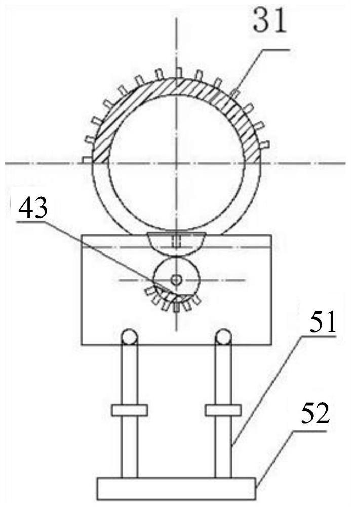
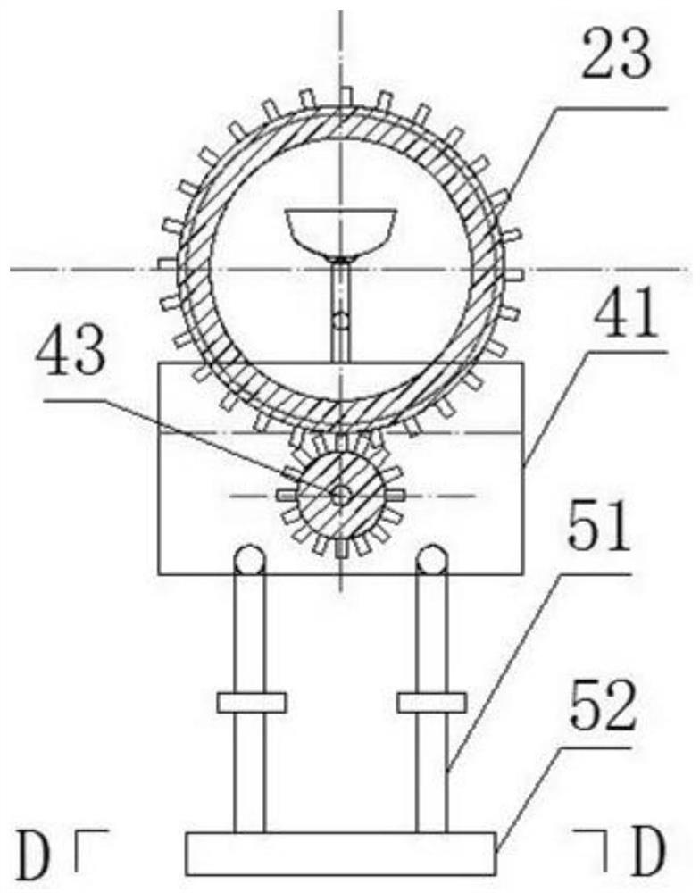
[0046] At least two support control components, which are respectively arranged at the feeding end and the discharging end of the transportation pipe body, control the forward rotation or reverse rotation of the transportation pipe body, and adjust the inclination angle of the transportation pipe body, so as to realize the conveying and mixing of concrete .

[0047] Such as figure 1 As shown, the transport pipe body in...


PUM


Abstract

The invention discloses a concrete conveying device, which comprises: a transportation pipe body and at least two supporting control components, wherein a plurality of spiral blades are arranged in the transportation pipe body; the spiral blades realize that concrete is maintained in an agitating state and cannot flow out the transportation pipe body when the transportation pipe body rotates clockwise, and the concrete flows out of the transportation pipe body when the transportation pipe body rotates counterclockwise; and the at least two supporting control components are respectively disposed at the feeding end and the discharging end of the transportation pipe body to control the clockwise rotation and the counterclockwise rotation of the transportation pipe body and adjust the inclination angle of the transportation pipe body, thereby realizing conveying and agitation of the concrete. The concrete conveying device realizes continuous pouring of the concrete, promotes the reductionof concrete pouring time, makes the super-pouring amount of the concrete easy to control, saves the labor and reduces the waste of the concrete.

Description

technical field [0001] The invention relates to the field of transportation machinery and equipment, in particular to a concrete conveying device. Background technique [0002] As a supporting enclosure structure, bored occlusal piles are widely used in the enclosure construction of deep foundation pits such as subway stations. The construction process of the occlusal pile mainly includes: guide wall construction, drilling, lowering the reinforcement cage, concrete pouring and other important processes. [0003] In the existing concrete pouring process, due to the casing drilling process, the position of the drilled hole is about 1.5-2 meters above the ground, so that the concrete pouring cannot be done in a self-unloading manner, and the pouring method of lifting materials with a large bucket is often used method, this kind of pouring method, in the process of on-site pouring, taking 10 cubic meters of concrete as an example, according to statistics, the pouring time is us...

Claims


Application Information

Patent Timeline
Patent Type & Authority Patents(China)
IPC IPC(8): E02D15/02
CPCE02D15/02
Inventor 周雨张先龙何占江敖飞陶冰杰李豪杰张执权吴胜利周辉
Owner SHANGHAI MARITIME UNIVERSITY
Why Eureka
Try Eureka