
Steel fiber automatic feeding device

An automatic feeding device and steel fiber technology, applied in vibrating conveyors, transportation and packaging, conveyors, etc., can solve problems affecting steel fiber production, material filtration and impurity removal, waste of manpower, etc.

Inactive Publication Date: 2019-04-19
ZHENGZHOU NEO LOOP TECH
View PDF0 Cites 1 Cited by
  • Summary
  • Abstract
  • Description
  • Claims
  • Application Information

AI Technical Summary

Problems solved by technology

The traditional steel fiber feeding device uses manual feeding, which is extremely wasteful of manpower, and does not filter and remove impurities from the material, which will affect the next step of steel fiber production. Therefore, we propose an automatic steel fiber feeding device

Method used


Image

  • Steel fiber automatic feeding device
  • Steel fiber automatic feeding device
  • Steel fiber automatic feeding device

Examples


Embodiment Construction

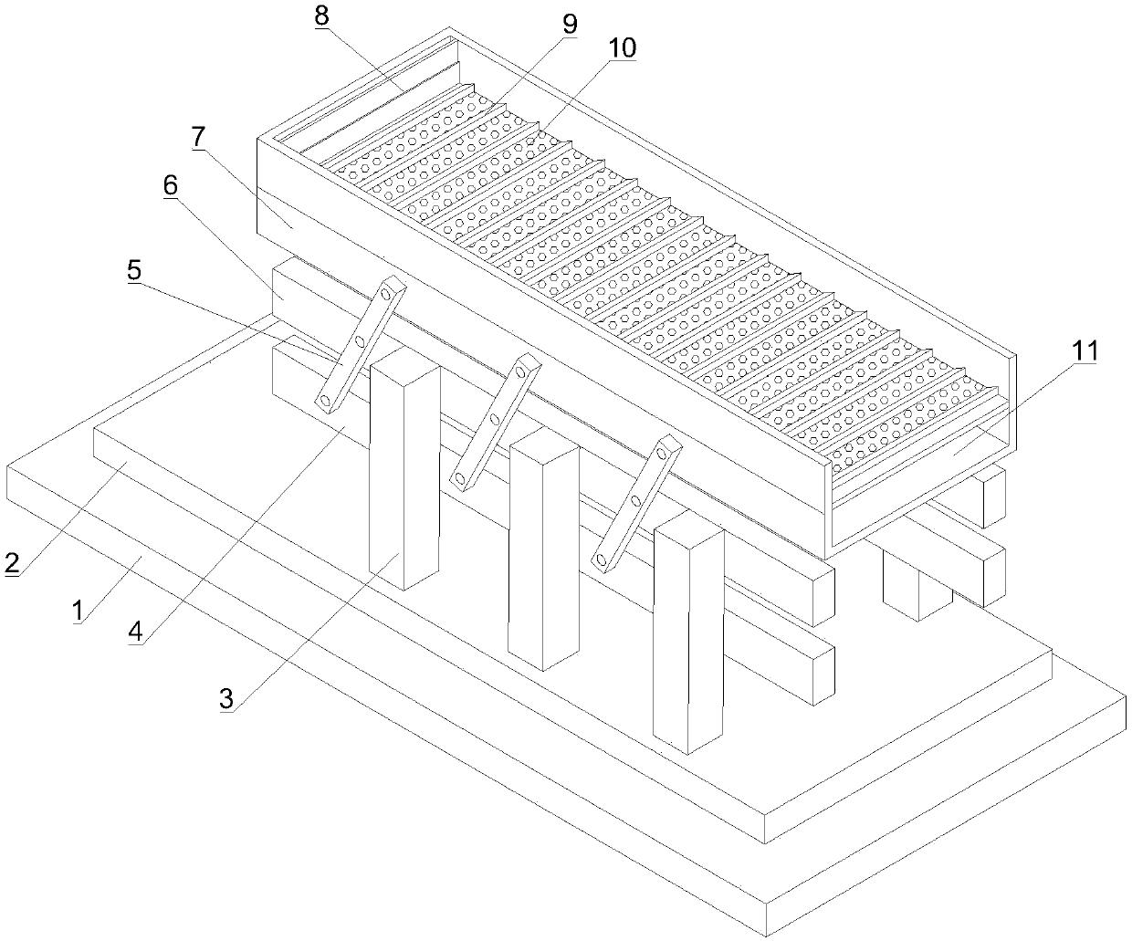
[0017] Such as Figure 1-4 as shown, figure 1 It is a structural schematic diagram of a steel fiber automatic feeding device proposed by the present invention.

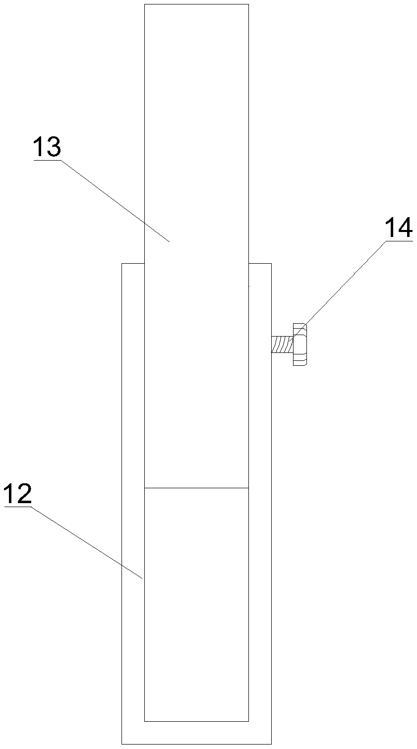
[0018] figure 2 It is a structural schematic diagram of a baffle plate in a steel fiber automatic feeding device proposed by the present invention.

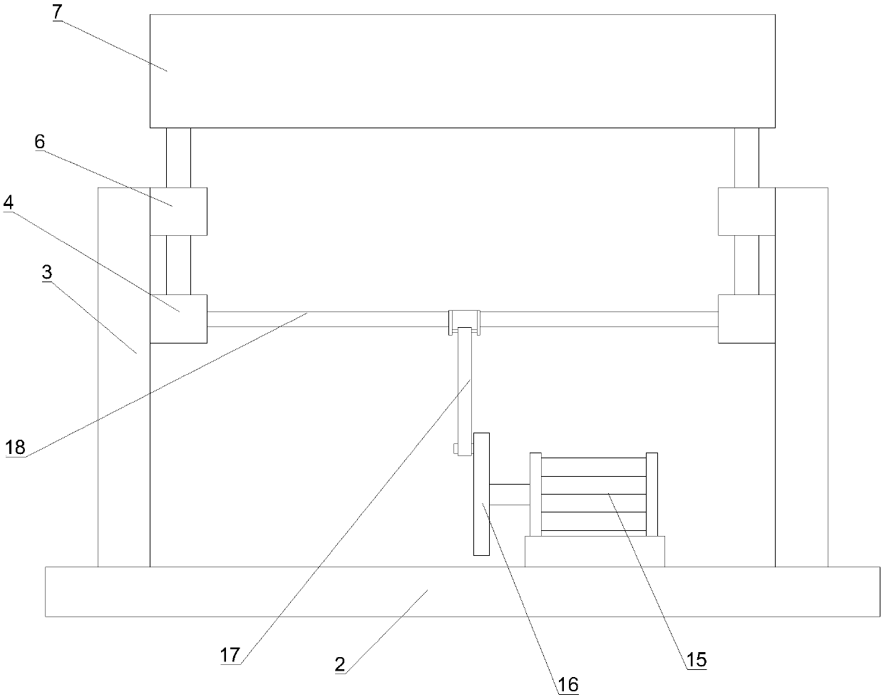
[0019] image 3 It is the middle left view of a steel fiber automatic feeding device proposed by the present invention.

[0020] Figure 4 It is a structural schematic diagram of a shock absorbing assembly in a steel fiber automatic feeding device proposed by the present invention.

[0021] refer to Figure 1-4 , a steel fiber automatic feeding device proposed by the present invention, including a base 1, a mounting base 2, a shock absorbing assembly, a leg 3, a first longitudinal beam 4, a swing arm 5, a second longitudinal beam 6, a vibration frame 7 and a slide plate 8. The mounting seat 2 is set above the base 1 and connected to the base 1 through a shock abs...


PUM


Abstract

The invention discloses a steel fiber automatic feeding device comprising a base, an installing seat, a vibration absorption assembly, support legs, first longitudinal beams, a swing arm, a second longitudinal beam, a vibration frame and a sliding plate. The installing seat is arranged on the base and is connected with the base through the vibration absorption assembly. The support legs are arranged on the installing seat side by side. The second longitudinal beam is fixedly installed at the tops of the inner sides of the support legs. A transverse rod is arranged between the first longitudinal beams. The output end of a vibration motor is connected with a rotary disc. The top end of a connecting rod is rotationally connected with the transverse rod. The bottom face of a support plate is connected with the base through an elastic part. A sliding rod is sleeved with a first spring. The bottom end of the first spring is connected with the base. The top end of the first spring is connected with the installing seat. The inner walls of the left and right sides of the base are provided with cylinder bodies. Third springs are arranged in the cylinder bodies. The other ends of the third springs are connected with a movable plate. The top end of the connecting rod is movably connected with the support plate. The bottom end of the connecting rod is connected with the movable plate. The steel fiber automatic feeding device has the advantages that automatic feeding is achieved, the weight of feeding of each time can be controlled, and filtration and purification can be conducted.

Description

technical field [0001] The invention relates to the technical field of automatic feeding, in particular to an automatic feeding device for steel fibers. Background technique [0002] Steel fiber refers to the length-to-diameter ratio (the ratio of the fiber length to its diameter) made by cutting fine steel wire, cold-rolled strip shearing, steel ingot milling or rapid condensation of molten steel. When the fiber cross-section is non-circular, the equivalent cross-sectional circle is used The diameter of the area) is 40 to 80 fibers. The properties of steel fibers produced by different preparation methods are also different. Although steel fiber came out not long ago, its application has become more and more extensive, and there are more and more types. The traditional steel fiber feeding device uses manual feeding, which is extremely wasteful of manpower, and does not filter and remove impurities from the material, which will affect the next step of steel fiber production...

Claims


Application Information

Patent Timeline
IPC IPC(8): B65G27/16B65G27/28
CPCB65G27/16B65G27/28
Inventor 牛欲晓王志刚刘自振王亚兵郝留军牛得晓
Owner ZHENGZHOU NEO LOOP TECH
Learn More