A rectifier with adjustable output voltage for wireless power transmission

A technology of wireless power transmission and output voltage, which is applied in the direction of output power conversion device, AC power input conversion to DC power output, electrical components, etc. It can solve the problems of non-adjustable output voltage, lower system efficiency, and increase production cost. To achieve the effect of simple circuit, reducing the number of components and reducing loss

Active Publication Date: 2020-01-24
甘肃南洋新能源科技发展有限公司
View PDF8 Cites 0 Cited by
  • Summary
  • Abstract
  • Description
  • Claims
  • Application Information

AI Technical Summary

Problems solved by technology

[0004] The purpose of the present invention is to solve the problem of low transmission efficiency caused by diode rectification loss at the wireless receiving end, and at the same time, the output voltage of diode rectification cannot be adjusted, which requires additional components, which reduces system efficiency and increases production costs. A rectifier with adjustable output voltage for wireless power transfer

Method used


Image

  • A rectifier with adjustable output voltage for wireless power transmission

Examples


Embodiment 1

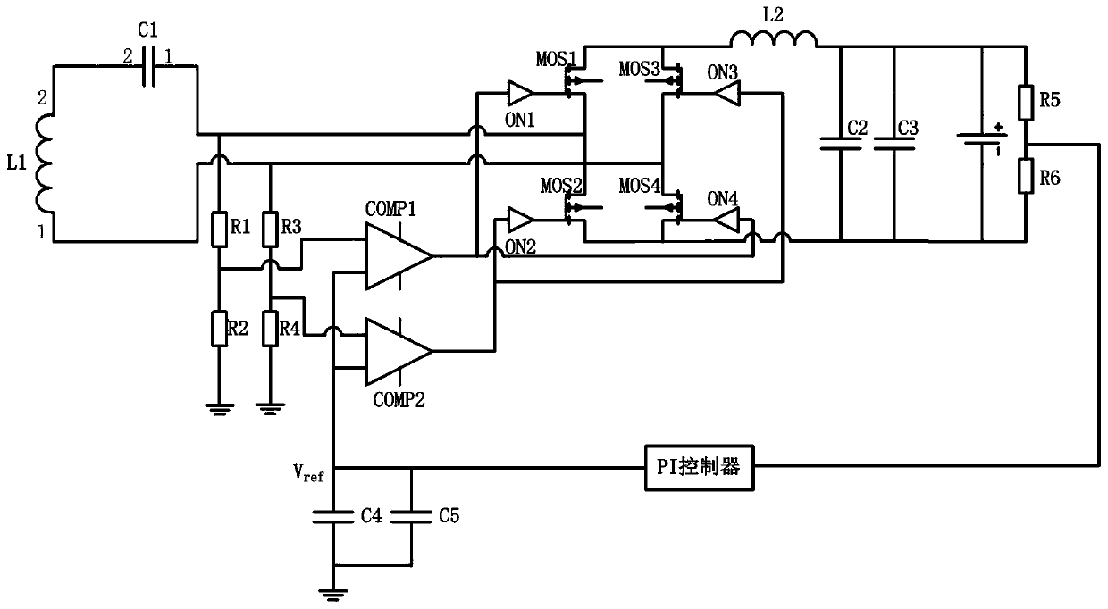
[0030] A rectifier with an adjustable output voltage for wireless power transmission provided by a preferred embodiment of the present invention, the front end of the rectifier is connected with a receiving coil L1 and a receiving compensation capacitor C1 connected in series, the rear end is connected with a load, and the rectifier consists of a MOS tube A bridge rectifier circuit composed of a synchronous signal detection circuit for detecting the input voltage and output voltage of the rectifier and controlling the output voltage of the rectifier.

[0031] Wherein, the bridge rectifier circuit includes MOS transistor 1, MOS transistor 2, MOS transistor 3, MOS transistor 4 and corresponding MOS transistor driving chips ON1, ON2, ON3 and ON4. Among them, the MOS transistor drive chips ON1, ON2, ON3 and ON4 can be replaced by drive circuits built with discrete components. The connection relationship of each component in the bridge rectifier circuit is as follows:

[0032] The...

Embodiment 2

[0046] On the basis of Embodiment 1, the back end of the bridge rectifier circuit is also connected with a filter and voltage regulator circuit for stabilizing and filtering the output voltage. The connected inductor L2 and the capacitors C2 and C3 connected in parallel with the load can stabilize and filter the output voltage through the inductor L2, capacitors C2 and C3. The circuit is simple, the design is reasonable, and the practicability is high.


PUM


Abstract

The invention discloses a rectifier with an adjustable output voltage for wireless electric energy transmission, and relates to the technical field of wireless power transmission. The front end of a rectifier is connected with a receiving coil and a receiving compensation capacitor, and the rear end of the rectifier is connected with a load. The rectifier comprises a bridge rectifier circuit and asynchronous signal detection circuit, and the bridge rectifier circuit comprises an MOS transistor 1, an MOS transistor 2, an MOS transistor 3, an MOS transistor 4 and corresponding MOS transistor driving chips ON1, ON2, ON3 and ON4. The synchronous signal detection circuit comprises a first-stage voltage division circuit used for collecting an input voltage of the rectifier, a second-stage voltage division circuit, a PI controller, a PWM, voltage comparators COMP1 and COMP2 and capacitors C4 and C5. The first-stage voltage division circuit comprises resistors R1, R2, R3 and R4, and the second-stage voltage division circuit comprises resistors R5 and R6. Through the combination of synchronous rectification and phase shift, the rectification loss of the wireless power transmission receiving end is reduced, and the production cost is reduced.

Description

technical field [0001] The invention relates to the technical field of wireless power transmission, in particular to a rectifier with adjustable output voltage for wireless power transmission. Background technique [0002] Wireless power transmission, also known as wireless power transmission, non-contact power transmission, refers to the conversion of electrical energy into other forms of relay energy through the transmitter, and after a distance is transmitted through the air, the relay energy is converted into electrical energy through the receiver to achieve Wireless power transmission. The wireless power transmission system includes a wireless transmitter and a wireless receiver that transmit energy through a magnetic field. The rectifier (rectifier) ​​at the wireless receiver is a device that converts alternating current into direct current. It can be used for power supply and radio signal detection. The rectifier can be made of vacuum tubes. , ignition tube, solid si...

Claims


Application Information

Patent Timeline
Patent Type & Authority Patents(China)
IPC IPC(8): H02M7/219H02J5/00
CPCH02J5/005H02M7/219
Inventor 张华张永恒
Owner 甘肃南洋新能源科技发展有限公司
Why Eureka
Try Eureka