


Quick Research
Generate reliable direction feasibility study reports for your R&D in just a few steps.

Technical Q&A
Discover and master advanced knowledge NOW. Basics, ideas, possibilities, all at once.

Find Solutions
As an expert in R&D theories, this can generate solutions to your technical problems instantly.

Evaluate Feasibility
Analyze your overall solution with one click, know your potential R&D risks in advance.

Monitor Landscape
Get weekly tech updates, stay abreast of the latest tech innovations and key insights.
Battery fixing structure, electric vehicle chassis and electric vehicle
A battery fixing, electric vehicle technology, applied in structural parts, battery pack parts, circuits, etc., can solve the problems of increased production cost, low connection reliability, easy deformation, etc., and achieves improved connection reliability, simple structure, Good carrying capacity
- Summary
- Abstract
- Description
- Claims
- Application Information
AI Technical Summary
Problems solved by technology
Method used
Image

Examples
Embodiment 1
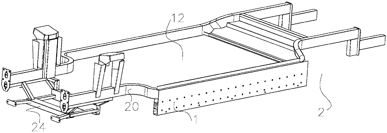
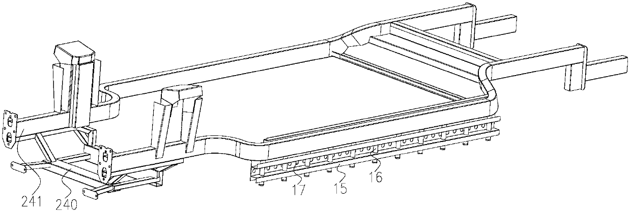
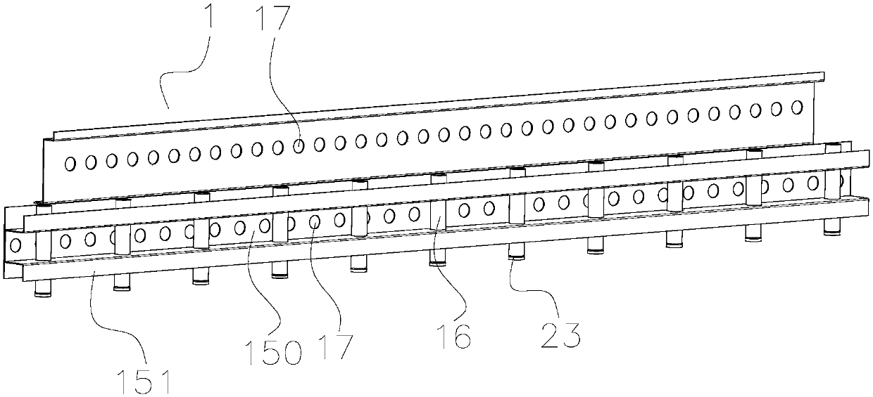
[0052] see Figure 1-Figure 4 As shown, the present embodiment provides a kind of acetabular prosthesis; figure 1 A structural schematic diagram of the battery fixing structure provided in this embodiment; figure 2 Another structural schematic diagram of the battery fixing structure provided in this embodiment, in order to clearly show the structural features inside the suspension plate, the third connecting plate is omitted; wherein, figure 1 with figure 2 It is a structural schematic diagram of the state where the battery fixing structure is arranged on the chassis of the electric vehicle, and the relative positional relationship between the battery fixing structure and the side beam of the frame can be clearly seen; image 3 It is a structural schematic diagram of the suspension plate of the battery fixing structure provided in this embodiment, Figure 4 A cross-sectional view of the suspension plate of the battery fixing structure provided in this embodiment.
[0053...
Embodiment 2
[0081] Embodiment 2 provides an electric vehicle chassis. This embodiment includes the battery fixing structure of Embodiment 1. The technical features of the battery fixing structure disclosed in Embodiment 1 are also applicable to this embodiment. The battery fixing structure disclosed in Embodiment 1 The technical characteristics of the structure will not be described repeatedly.
[0082] combine Figure 1 to Figure 4 , see Figure 5 This embodiment provides an electric vehicle chassis 2 . Figure 5 A schematic structural view of the support frame 24 of the electric vehicle chassis 2 provided in this embodiment is shown.
[0083] The electric vehicle chassis 2 provided in this embodiment includes: a vehicle frame and two side beams 20, the two side beams 20 are arranged side by side on the vehicle frame along the transverse direction of the vehicle body, and the side beams 20 extend along the longitudinal direction of the vehicle body on the vehicle frame , the side beam...
PUM
 Abstract
Description
Claims
Application Information
 - R&D Engineer
- R&D Manager
- IP Professional
- Industry Leading Data Capabilities
- Powerful AI technology
- Patent DNA Extraction
Browse by: Latest US Patents, China's latest patents, Technical Efficacy Thesaurus, Application Domain, Technology Topic, Popular Technical Reports.
© 2024 PatSnap. All rights reserved.Legal|Privacy policy|Modern Slavery Act Transparency Statement|Sitemap|About US| Contact US: help@patsnap.com