
A method for testing the magnetic induction intensity of steel plate welding magnetic deflection blowing sensitivity

A technology of magnetic induction and magnetic deflection, applied in the direction of the size/direction of the magnetic field, magnetic performance measurement, etc., can solve the problems of complexity, inflexibility and convenience, and consume a lot of manpower and material resources, and achieve the effect of simple equipment and accurate measurement

Active Publication Date: 2020-09-25
JIANGYIN XINGCHENG SPECIAL STEEL WORKS CO LTD
View PDF5 Cites 0 Cited by
  • Summary
  • Abstract
  • Description
  • Claims
  • Application Information

AI Technical Summary

Problems solved by technology

[0007] In research at home and abroad, there are many measures and methods for welding in a magnetic field environment, but they are all complicated or inflexible and convenient. After on-site welding practice, the effect is not ideal
[0008] For a long time, the welding magnetic deflection problem can only be analyzed qualitatively and how to improve after the magnetic deflection occurs. There is no simple and effective method for quantitative detection of the strength of the steel plate welding magnetic deflection sensitive magnetic steel, so it is impossible to provide on-site Appropriate residual magnetism control range; when the steel plate produces residual magnetism, it is almost impossible to completely eliminate the residual magnetism of the steel plate, and the elimination of residual magnetism consumes a lot of manpower and material resources
Excessive residual magnetism of the steel plate will produce magnetic deflection blowing, which will affect the welding quality

Method used


Image

  • A method for testing the magnetic induction intensity of steel plate welding magnetic deflection blowing sensitivity
  • A method for testing the magnetic induction intensity of steel plate welding magnetic deflection blowing sensitivity
  • A method for testing the magnetic induction intensity of steel plate welding magnetic deflection blowing sensitivity

Examples


Embodiment Construction

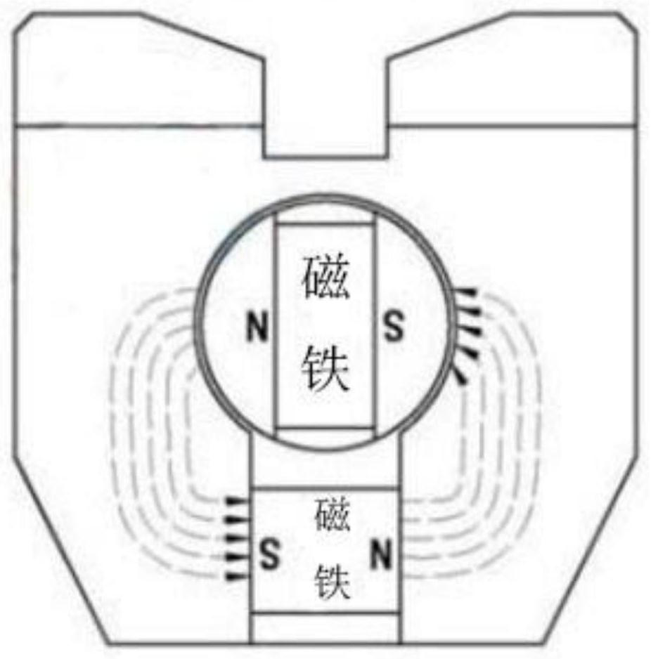
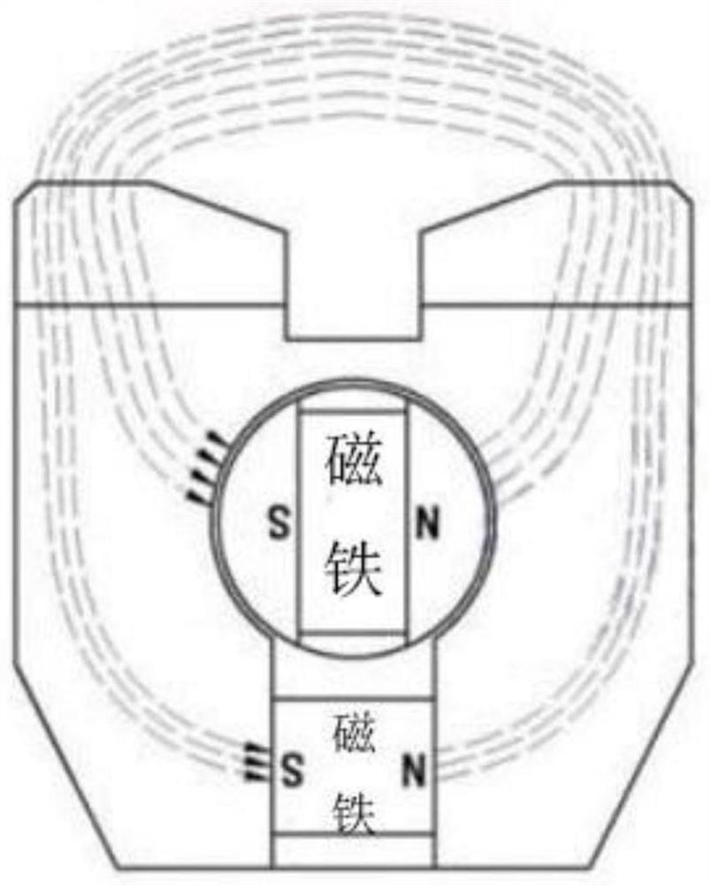
[0036] Exemplary embodiments of the present disclosure will be described in more detail below with reference to the accompanying drawings. Although exemplary embodiments of the present disclosure are shown in the drawings, it should be understood that the present disclosure may be embodied in various forms and should not be limited by the embodiments set forth herein. Rather, these embodiments are provided for more thorough understanding of the present disclosure and to fully convey the scope of the present disclosure to those skilled in the art.

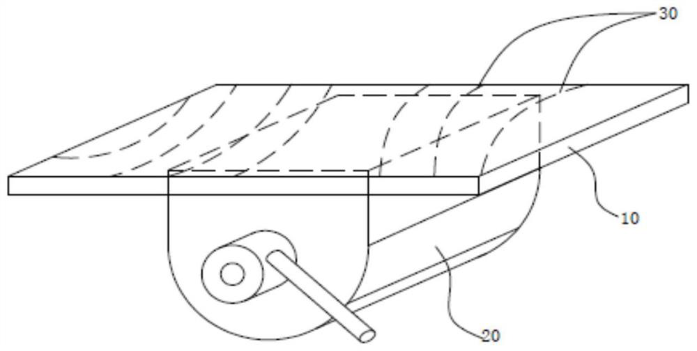
[0037] like Figure 1-3 As shown, the method for checking the magnetic deflection blowing sensitive magnetic induction intensity of steel plate welding specifically includes the following steps:

[0038] Process the steel plate to a suitable size. The size of the steel plate should be controlled within a reasonable range, for example, the length is 350mm-600mm, the width is 150mm-300mm, and the thickness is not more than 50mm. For...


PUM

PropertyMeasurementUnit
lengthaaaaaaaaaa
widthaaaaaaaaaa
thicknessaaaaaaaaaa

Abstract

The invention discloses a method for detecting the strength of the magnetic blowing sensitive magnetic induction intensity of steel plate welding. The method comprises the following steps that a steelplate is machined to a proper size; magnetizing treatment is carried out on the steel plate; a plurality of Nth isomagnetic lines are drawn taken the gap along a Nth magnetic field as the interval onthe surface of the magnetized steel plate; welding is performed along the order of the magnetic fields from strong to weak and along along the multiple Nth isomagnetic lines, the magnetic blowing condition during the welding is observed, and then the magnetic blowing sensitive magnetic induction intensity is determined; and a metallographic sample is extracted from a weld joint of the magnetic blowing sensitive magnetic induction intensity determined in the above steps, and defect detection is carried out on the metallographic sample to determine the magnetic blowing sensitive magnetic induction intensity. According to the method, the magnetic blowing sensitive magnetic induction intensity generated by the residual magnetism of the steel plate can be simply and effectively found, the residual magnetism of the steel plate is controlled to be in the sensitive magnetic induction intensity or below before the welding, the phenomenon of magnetic blowing in the welding process is avoided, the welding quality of the steel plate is guaranteed, and excessive demagnetization is not needed and the waste of manpower and financial resources is caused.

Description

technical field [0001] The invention relates to the field of welding, in particular to a method for testing the magnetic induction intensity of magnetic deflection blowing sensitivity of steel plate welding. . Background technique [0002] The welding arc is essentially a flexible gas with a certain degree of ionization. It is neutral macroscopically, but it is composed of charged particles of cations and electrons, neutral particles of atoms and molecules in the microcosm. The cations and electrons move in a certain direction to form a current. , creating a magnetic field around the arc. Therefore, if the uniform distribution of the self-generated magnetic field is destroyed for some reason, the arc will deviate from the axial direction of the electrode (wire) due to the uneven force, that is, the phenomenon of magnetic blowing occurs. [0003] As is known, in general, in order to prevent magnetic deflection, the following scheme is usually adopted: [0004] 1. Generally...

Claims


Application Information

Patent Timeline
Patent Type & Authority Patents(China)
IPC IPC(8): G01R33/02G01R33/12
CPCG01R33/02G01R33/12
Inventor 刘振伟白云鲍雪君孙鸣华杨烽
Owner JIANGYIN XINGCHENG SPECIAL STEEL WORKS CO LTD
Learn More