Winding structure wall pipe with positioning structure and production process thereof

A technology for positioning structure and structural wall pipe, applied in the direction of pipe, rigid pipe, pipeline protection, etc., can solve the problems of long construction time, damage, affecting normal use, etc., to improve construction efficiency, read and write information accurately, and ensure qualified sexual effect

Pending Publication Date: 2019-04-16
王利群
View PDF0 Cites 2 Cited by
  • Summary
  • Abstract
  • Description
  • Claims
  • Application Information

AI Technical Summary

Problems solved by technology

The disadvantage of this method is that the on-site construction time is long, the operation is inconvenient, and the slotting position is easy to damage the pipe body, causing damage and leakage, and it is easy to damage the electronic marker when the welding torch is sealed, affecting normal use.

Method used


Image

  • Winding structure wall pipe with positioning structure and production process thereof
  • Winding structure wall pipe with positioning structure and production process thereof
  • Winding structure wall pipe with positioning structure and production process thereof

Examples


Embodiment 1

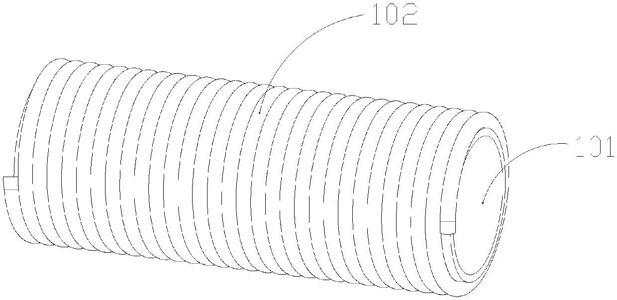
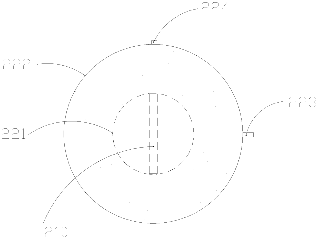
[0043] Such as figure 1 and figure 2 As shown, a winding structure wall pipe with a positioning structure includes a main body formed by connecting one or more branch pipe bodies 101 and a rib pipe 102 spirally and equidistantly wound from one end of the outer wall of the branch pipe body 101 to the other end. The two ends of the rib tube 102 are closed or narrowed, and one end of the inner cavity of the rib tube 102 is filled with a positioning structure for locating the geographical position of the branch body 101. The positioning structure includes an electronic marker 210, and the electronic marker The outer seal of 210 is wrapped with a heat insulation layer, and the outer surface of the heat insulation layer is an elastic structure that can be squeezed by the inner cavity of the finned tube 102 to fix its relative position with the finned tube 102 .

[0044] For the structure of the heat insulation layer, a liquid capsule is used, and the thermal conductivity of the li...

Embodiment 2

[0063] Such as figure 1 and figure 2 As shown, a winding structure wall pipe with a positioning structure includes a main body formed by connecting one or more branch pipe bodies 101 and a rib pipe 102 spirally and equidistantly wound from one end of the outer wall of the branch pipe body 101 to the other end. The two ends of the rib tube 102 are closed or narrowed, and one end of the inner cavity of the rib tube 102 is filled with a positioning structure for locating the geographical position of the branch body 101. The positioning structure includes an electronic marker 210, and the electronic marker The outer seal of 210 is wrapped with a heat insulation layer, and the outer surface of the heat insulation layer is an elastic structure that can be squeezed by the inner cavity of the finned tube 102 to fix its relative position with the finned tube 102 .

[0064] For the structure of the heat insulation layer, a gaseous bag is used, and the thermal conductivity of the gas i...

Embodiment 3

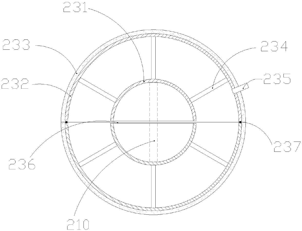
[0083] Based on Embodiment 1 or Embodiment 2, the thermal insulation bag is in a spherical or cylindrical structure after being expanded. It is preferably a cylindrical structure, the axial direction of which is the same as the axial direction of the rib tube 102, and can have a larger contact area with the rib tube 102. Prevent the positioning structure from moving.


PUM

PropertyMeasurementUnit
Thicknessaaaaaaaaaa

Abstract

The invention discloses a winding structure wall pipe with a positioning structure, and provides a production process of stably burying a positioning structure at a time in the pipe production. The structure wall pipe comprises a main pipe body formed by connecting one or more segments of branch pipe bodies and ribbed pipes winding spirally and at equal distances from one ends of the outer walls of the branch pipe bodies to the other ends, and the two ends of the ribbed pipes are closed or indented. One ends of inner cavities of the ribbed pipes are filled with positioning structures for positioning the geographical position of the branch pipe bodies, the positioning structures comprise electronic identification devices, and the electronic identification device are covered with thermal insulation layers in a sealing mode. The outer surfaces of the thermal insulation layers are elastic structures which can be extruded by the inner cavities of the ribbed pipes and capable of being fixedto the relative position of the ribbed pipes. The structure wall pipe improves the construction efficiency, enables the positioning and reading and writing information to be more accurate, and can avoid damage to the pipe.

Description

technical field [0001] The invention relates to the technical field of pipe material positioning, in particular to a winding structure wall pipe with a positioning structure and a production process thereof. Background technique [0002] At present, there are six main methods for finding and locating underground plastic pipelines, namely, paper as-built drawings, geographic information systems, pipeline detectors, underground electronic marking systems, surface markings, and underground electronic marking systems. [0003] Among them, the paper as-built drawing is not easy to save, and the pipeline diagram is not easy to update; the maintenance cost of the geographic information system is relatively high in practical applications; the pipeline detector is easily disturbed by the adjacent pipeline, and the wire tracer line laid in the plastic pipeline is easy to break; Surface signs are easily lost and damaged. The underground electronic marking system will not be disturbed ...

Claims


Application Information

Patent Timeline
IPC IPC(8): F16L9/16F16L47/03F16L59/02B29C69/00B29L23/00
CPCF16L9/16F16L47/03F16L59/02F16L59/028B29C69/002B29L2023/00
Inventor 王利群
Owner 王利群
Why Eureka
Try Eureka