


Quick Research
Generate reliable direction feasibility study reports for your R&D in just a few steps.

Technical Q&A
Discover and master advanced knowledge NOW. Basics, ideas, possibilities, all at once.

Find Solutions
As an expert in R&D theories, this can generate solutions to your technical problems instantly.

Evaluate Feasibility
Analyze your overall solution with one click, know your potential R&D risks in advance.

Monitor Landscape
Get weekly tech updates, stay abreast of the latest tech innovations and key insights.
An easy-to-install power pole tower
A technology of power towers and installation columns, applied in the field of easy-to-install power towers, can solve the problems of easy toppling, unstable foundation of towers, unstable installation of towers, etc.
- Summary
- Abstract
- Description
- Claims
- Application Information
AI Technical Summary
Problems solved by technology
Method used
Image

Examples
Embodiment 1
[0043] Embodiment 1 Easy-to-install electric power tower
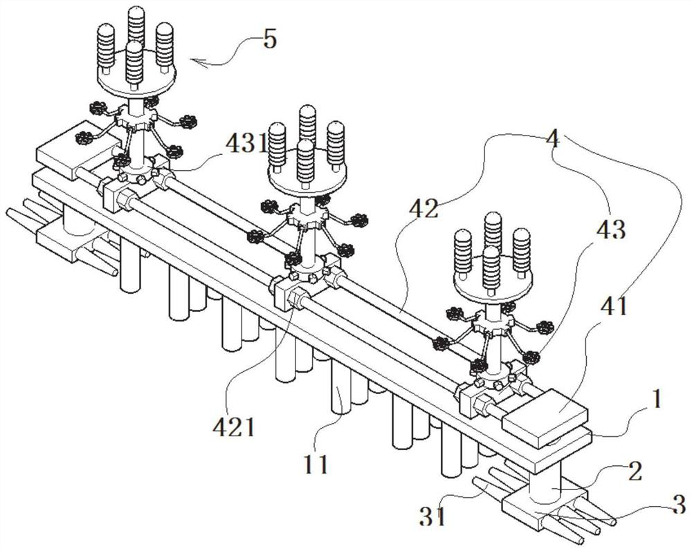
[0044] Such as Figure 1-8 As shown, an easy-to-install power pole tower includes an installation base plate 1, and several embedded bolts 11 are fixedly connected to the bottom of the installation base plate 1;
[0045] The carriage part 4 includes end seats 41 located on the left and right sides of the mounting seat plate 1, and two sliding screws 42 are fixedly connected between the end seats 41; The sliding seat 43 ; several positioning nuts 421 are threadedly connected to the sliding screw rod 42 , and the positioning nuts 421 are squeezed and positioned on the left and right sides of the sliding seat 43 .
[0046] Loosen the positioning nut 421 to adjust the distance between the sliding seats 43 at adjacent parts, and then adjust the installation distance according to the actual installation process.
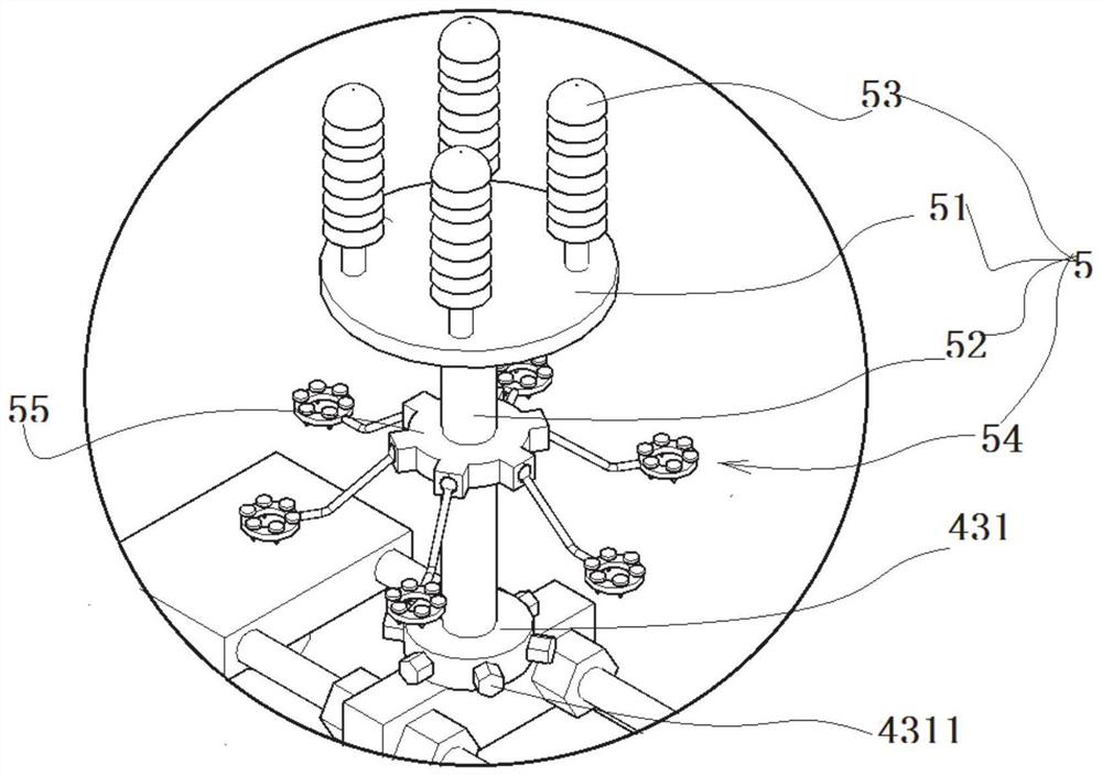
[0047] The top of the above-mentioned sliding seat 43 is fixedly connected with a power pole and tower part 5;...
Embodiment 2
[0063] Embodiment 2 Installation method
[0064] Such as Figure 1-8 As shown, the structure of the device disclosed in this embodiment is the same as that disclosed in Embodiment 1, and the installation method is disclosed. An easy-to-install power pole and tower includes an installation base plate 1, the bottom of which is fixedly connected with several embedded bolts 11; the top of the installation base plate 1 is equipped with a carriage component 4.
[0065] The carriage part 4 includes end seats 41 located on the left and right sides of the mounting seat plate 1, and two sliding screws 42 are fixedly connected between the end seats 41; The sliding seat 43 ; several positioning nuts 421 are threadedly connected to the sliding screw rod 42 , and the positioning nuts 421 are squeezed and positioned on the left and right sides of the sliding seat 43 .
[0066] Loosen the positioning nut 421 to adjust the distance between the sliding seats 43 at adjacent parts, and then adjus...
PUM
 Abstract
Description
Claims
Application Information
 - R&D Engineer
- R&D Manager
- IP Professional
- Industry Leading Data Capabilities
- Powerful AI technology
- Patent DNA Extraction
Browse by: Latest US Patents, China's latest patents, Technical Efficacy Thesaurus, Application Domain, Technology Topic, Popular Technical Reports.
© 2024 PatSnap. All rights reserved.Legal|Privacy policy|Modern Slavery Act Transparency Statement|Sitemap|About US| Contact US: help@patsnap.com