
A medical detection glass tube delivery device

A conveying device and glass tube technology, which is applied in the field of medical supplies, can solve the problems of broken glass tubes, scratched hands of staff, scratches or shatters of glass tubes, etc., so as to save equipment costs, prevent slipping, and prevent jamming. Effect

Inactive Publication Date: 2020-09-22
THE AFFILIATED HOSPITAL OF QINGDAO UNIV
View PDF7 Cites 0 Cited by
  • Summary
  • Abstract
  • Description
  • Claims
  • Application Information

AI Technical Summary

Problems solved by technology

[0002] Bottle stoppers with glass tubes are a very common tool in the field of medical testing. In the current assembly and production of glass tubes and bottle stoppers, most manufacturers manually assemble glass tubes and bottle stoppers together. Low work efficiency and high labor costs. During assembly, glass tubes are often broken due to improper assembly methods, increasing the scrap rate of scrap production, and often scratching or stabbing the hands of the staff
A small number of manufacturers will insert the glass tube into the bottle stopper through automatic assembly, so that the glass tube will often break or break when the glass tube and the bottle stopper are assembled in production; the depth of the glass tube inserted into the bottle stopper is not enough Or the depth cannot be consistent, and the assembly accuracy and stability are low; the glass tube is not stable enough in the process of conveying, and it is easy to generate strong vibration or cause relatively large friction between the glass tube and other equipment, which will easily cause the glass tube to be scratched during transportation. marks or shattering; multiple mechanical claws or a lot of positioning detection equipment will be used in the assembly, the assembly process is too cumbersome

Method used


Image

  • A medical detection glass tube delivery device
  • A medical detection glass tube delivery device
  • A medical detection glass tube delivery device

Examples


Embodiment Construction

[0025] In order to make the present invention more obvious and understandable, the detailed description is as follows in conjunction with the accompanying drawings.

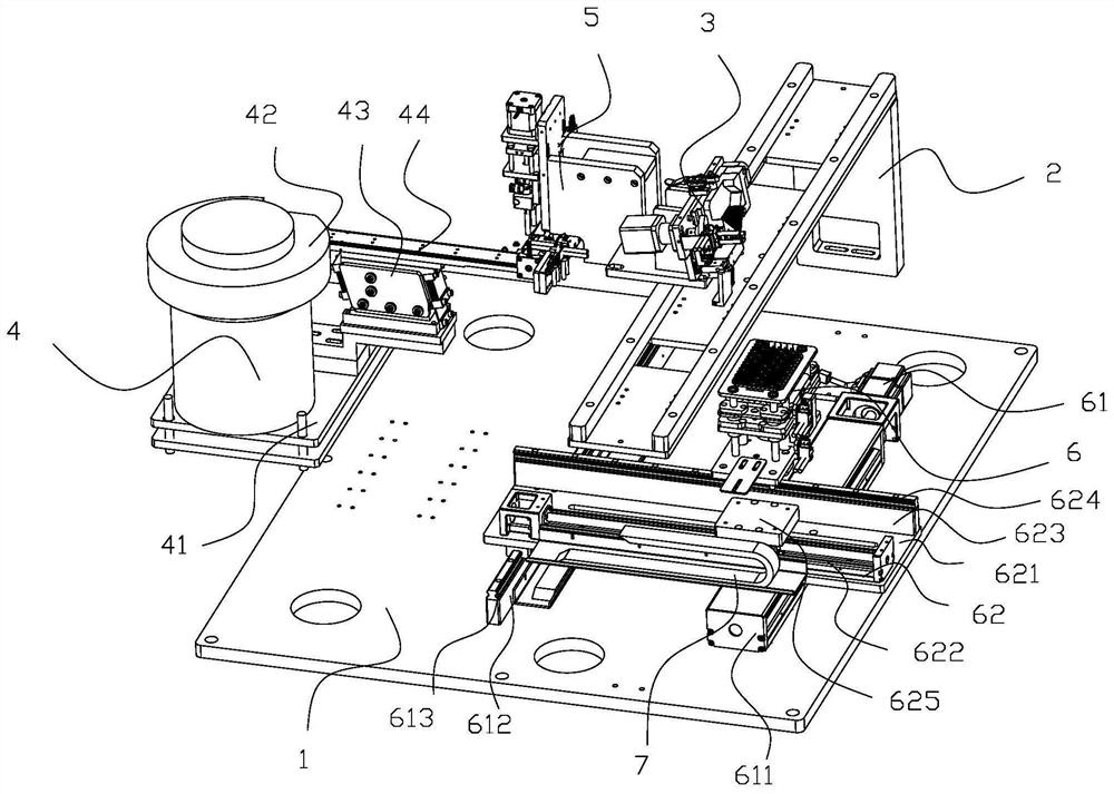
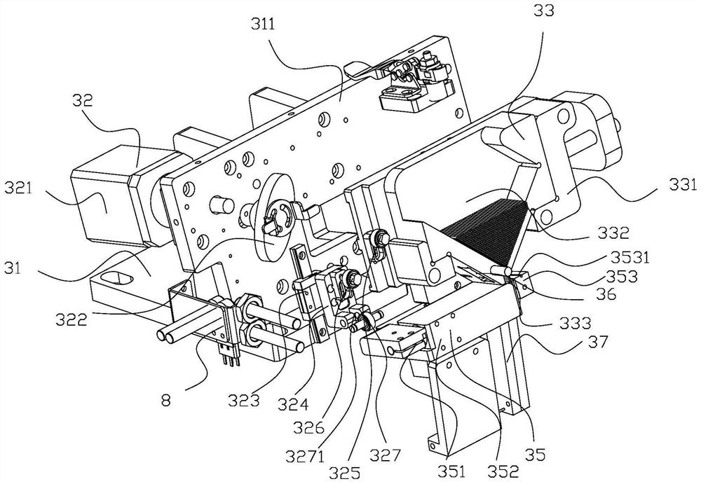
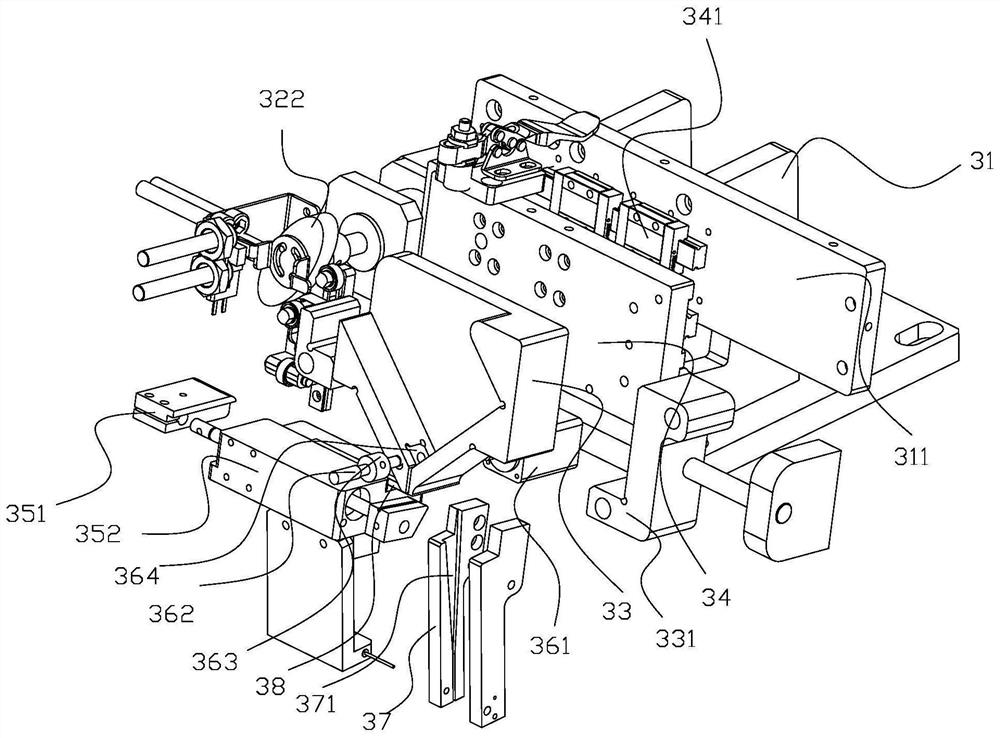
[0026] Such as figure 1 As shown, an automatic assembly equipment for glass tubes for medical detection corks, the equipment includes a support plate 1, a gantry frame 2, a glass tube conveying device 3, a cork feeding device 4, a cork conveying device 5 and an assembly device 6; the gantry The frame 2 is arranged on the support plate 1; the glass tube conveying device 3 is arranged on the gantry frame, and the glass tube conveying device 4 is used to convey the glass tube to the assembly device 6; the bottle stopper feeding device 4 is arranged on the support plate 1, The discharge end of the cork feeding device 4 is connected with the feeding end of the cork conveying device 5, and the cork feeding device 4 is used to convey the cork to the cork conveying device 5; the cork conveying device 5 is arranged on On...


PUM


Abstract

The invention relates to the technical field of medical supplies. A medical testing glass tube conveying device comprises a glass tube conveying support, a glass tube drive module, a glass tube carrier plate, a carrier plate connecting plate and a glass tube guiding module. The glass tube drive module can drive the carrier plate connection plate to move leftwards and rightwards. The carrier plateconnection plate is in sliding connection with an oblique plate through a carrier sliding rail. The carrier plate connection plate is provided with a coordination fixing block. One side of the coordination fixing block is connected with a coordination reset spring. The coordination reset spring is fixedly connected with the oblique plate through a spring fixing block. The glass tube carrier plateis provided with a guiding-in module, and the glass tube drive module can enable the glass tube guiding module to rotate and guide a glass rod into a glass tube material receiving rod. The medical testing glass tube conveying device has the beneficial effects that firstly, a glass tube is inserted, then, a bottle stopper is inserted into the glass tube, and the insertion depth of the glass tube can be effectively controlled; the glass tube can be prevented from sliding down; and the glass tube carrier plate can be driven to stably move, and the guiding-in module is driven to carry out effective guiding.

Description

technical field [0001] The invention relates to the technical field of medical supplies, in particular to a medical detection glass tube delivery device and automatic assembly equipment. Background technique [0002] Bottle stoppers with glass tubes are a very common tool in the field of medical testing. In the current assembly and production of glass tubes and bottle stoppers, most manufacturers manually assemble glass tubes and bottle stoppers together. The work efficiency is low, the labor cost is high, and the glass tube is often broken due to improper assembly method during assembly, which increases the scrap rate of scrap production, and often scratches or stabs the hands of the staff. A small number of manufacturers will insert the glass tube into the bottle stopper through automatic assembly, so that the glass tube will often break or break when the glass tube and the bottle stopper are assembled in production; the depth of the glass tube inserted into the bottle sto...

Claims


Application Information

Patent Timeline
Patent Type & Authority Patents(China)
IPC IPC(8): B65G35/00B65G47/44B65G27/02B65G47/91B67B1/04
CPCB65G27/02B65G35/00B65G47/44B65G47/912B67B1/04
Inventor 程宽董娴宁康恩豪王小华
Owner THE AFFILIATED HOSPITAL OF QINGDAO UNIV
Learn More