Eureka AIR delivers breakthrough ideas for toughest innovation challenges, trusted by R&D personnel around the world.

Multi-connecting-rod suspension mechanism for front and rear universal use in vehicle driven by wheel hub motor and

A hub motor and multi-link technology, applied in the direction of suspension, elastic suspension, vehicle components, etc., can solve the problems of large unsprung mass, unreasonable layout, insufficient space for hub motor suspension layout, etc., to reduce the development cycle , compact suspension structure, good application prospects and market value

Pending Publication Date: 2019-04-16
KH AUTOMOTIVE TECH CHANGCHUN
View PDF0 Cites 7 Cited by
  • Summary
  • Abstract
  • Description
  • Claims
  • Application Information

AI Technical Summary

Problems solved by technology

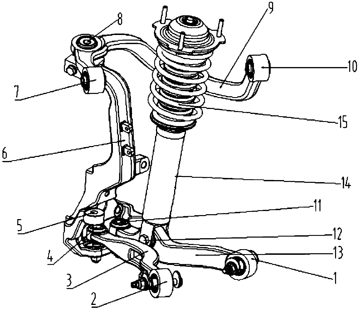
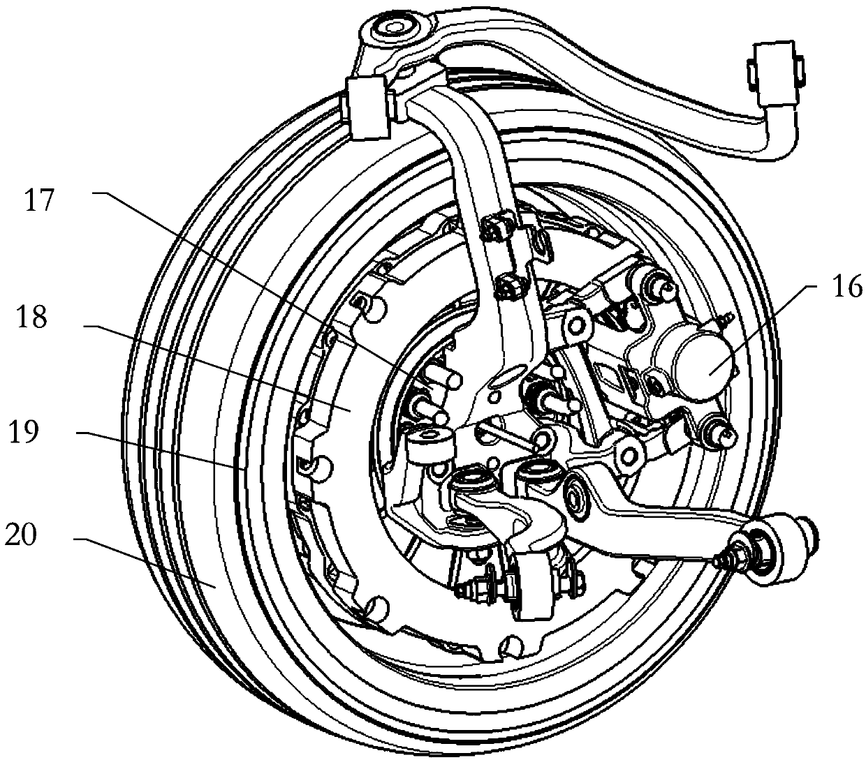
[0004] The purpose of the present invention is to provide a new type of suspension matching with the wheel hub motor, and the outer ball of the lower control link is hinged in the brake disc to make the suspension structure more compact and provide a larger layout for other chassis systems Space, solve the defects of insufficient space for hub motor suspension layout and large unsprung mass, overcome the problem of unreasonable layout of hub motor suspension kingpins, and obtain good stability performance

Method used


Image

  • Multi-connecting-rod suspension mechanism for front and rear universal use in vehicle driven by wheel hub motor and
  • Multi-connecting-rod suspension mechanism for front and rear universal use in vehicle driven by wheel hub motor and
  • Multi-connecting-rod suspension mechanism for front and rear universal use in vehicle driven by wheel hub motor and

Examples


Embodiment Construction

[0025] The present invention will be further described in detail below in conjunction with the drawings and specific embodiments.

[0026] Such as figure 1 As shown, the in-wheel motor-driven multi-link suspension mechanism of the present invention is universal for the front and rear of the vehicle, including a steering knuckle assembly 6, a lower front control link 13, a lower rear control link 3, an upper control arm assembly 9, The damper assembly 14 and the spring 15, the steering knuckle assembly 6 and the upper control arm assembly 9 are articulated and articulated through the upper control arm outer spherical hinge 8; the steering knuckle assembly 6 and the lower front control link 13 pass through the lower The outer ball hinge 11 of the front control link is hingedly connected; the steering knuckle assembly 6 and the lower rear control link 3 are hingedly connected by the outer ball hinge 4 of the lower rear control link;

[0027] The upper control arm assembly 9 is hingedl...


PUM


Abstract

The invention discloses a multi-connecting-rod suspension mechanism for front and rear universal use in a vehicle driven by a wheel hub motor. The multi-connecting-rod suspension mechanism comprises asteering knuckle assembly, a lower front control connecting rod, a lower rear control connecting rod, an upper control arm assembly, a damper assembly and a spring, and the steering knuckle assemblyis hinged to the upper control arm assembly through an upper control arm outer ball hinge; the steering knuckle assembly is hinged to the lower front control connecting rod through a lower front control connecting rod outer ball hinge; the steering knuckle assembly is hinged to the lower rear control connecting rod through a lower rear control connecting rod outer ball hinge. The multi-connecting-rod suspension mechanism overcomes the limitations of insufficient space and large unsprung mass of a wheel hub motor suspension frame, the structure of the suspension frame is more compact, and the controllability and stability are better; a driving mechanism, a partial guiding mechanism and a braking device are all integrated into a wheel hub, so that the multi-connecting-rod suspension mechanism has the advantage of high integration degree, the general platform design of the whole vehicle is facilitated, the development cycle is greatly shortened, and the production line cost and the industrial chain scale can be greatly reduced; thus, the multi-connecting-rod suspension mechanism has good application prospects and high market value.

Description

Technical field [0001] The technical field of automobile chassis of the present invention particularly relates to a universal multi-link suspension mechanism for front and rear driving vehicles of a wheel hub motor. Background technique [0002] In-wheel motor technology is to directly arrange the motor assembly integrated with the reducer in the hub, and 4 wheel motors directly drive 4 wheels. Compared with traditional electric vehicles, the in-wheel motor technology eliminates the need for differentials and half Axle and even two-stage transmission, the whole vehicle structure has been greatly simplified. However, compared to vehicles driven by internal combustion engines or traditional centralized motors, the various parts of the wheel suspension driven by in-wheel motors, such as control arms, shock absorbers, springs, etc., are tightly arranged, causing the chassis system to easily interfere. It is difficult to adapt the frame to match. [0003] In addition, the unsprung mas...

Claims


Application Information

Patent Timeline
Patent Type & Authority Applications(China)
IPC IPC(8): B60G3/20B60G15/02
CPCB60G3/20B60G15/02B60G2204/30B60G2204/149
Inventor 郭孔辉仇韬李野
Owner KH AUTOMOTIVE TECH CHANGCHUN
Why Eureka
Eureka Blog
Learn More