
Special fixtures for transmission control device shell lathe and machining method

A technology for manipulating devices and special fixtures, applied in positioning devices, metal processing equipment, metal processing machinery parts, etc., can solve the problems of high production cost of special knives and tooling, low processing efficiency, poor positioning of parts, etc., and achieve the cost of fixture production Low cost, easy maintenance, no deformation and embossing effect

Inactive Publication Date: 2019-04-16
XIANYANG SHENGYA ELECTROMECHANICAL EQUIP CO LTD
View PDF6 Cites 0 Cited by
  • Summary
  • Abstract
  • Description
  • Claims
  • Application Information

AI Technical Summary

Problems solved by technology

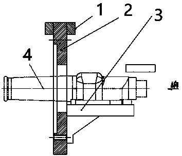
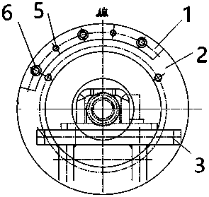
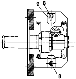
The main defects and deficiencies include: the boring processing equipment in the prior art has high cost, low processing efficiency, high production cost of special tools and tooling, high maintenance cost, complex adjustment of tools and fixtures, poor part positioning, and slow clamping speed , Dimensional instability after processing and other defects, the special jig for boring processing of special-shaped parts in the prior art cannot adapt to mass production, resulting in high production costs, so there is an urgent need to design a low-cost, easy-to-use and maintenance-cost Low profile special-shaped parts boring processing special fixture

Method used


Image

  • Special fixtures for transmission control device shell lathe and machining method
  • Special fixtures for transmission control device shell lathe and machining method
  • Special fixtures for transmission control device shell lathe and machining method

Examples


Embodiment Construction

[0030] The present invention will be further explained below in conjunction with the accompanying drawings and specific embodiments. It should be understood that the following specific embodiments are only used to illustrate the present invention and are not intended to limit the scope of the present invention. In the description of the present invention, it should be noted that the terms "center", "upper", "lower", "left", "right", "vertical", "horizontal", "inner", "outer", The orientation or positional relationship indicated by "top", "bottom", etc. are based on the orientation or positional relationship shown in the drawings, and are only for the convenience of describing the present invention and simplifying the description, rather than indicating or implying that the referred device or element must have Certain orientations, constructed and operative in certain orientations, therefore are not to be construed as limitations on the invention. In addition, unless otherwise ...


PUM


Abstract

The invention relates to the field of machining, in particular to special fixtures for a transmission control device shell lathe and a machining method. The two fixtures, namely a clamping structure Aand a clamping structure B, are installed on spindles of two SK50P digital controlled lathes separately, both ends of a part are machined separately through two-times clamping, and the requirements of the size of both ends of the part and the coaxiality being 0.05 of both ends are ensured. A flange plate is fixedly connected with machining equipment through fastening screws, so that the part is located at a correct and efficient position, after the part of a control device shell is positioned, a fast clamping mechanism is used for fast clamping of the part; the part is fixed efficiently; after machining is finished, a pressing plate clamping state is opened, and the part of the control device shell can be taken down; and then machining of the other end is completed on another equipment following the same steps.

Description

technical field [0001] The invention relates to the field of mechanical processing, in particular to a special clamp and a processing method for a transmission manipulator casing lathe. Background technique [0002] The shape of the workpiece to be processed is complex, and the end faces and boring holes at both ends of the special-shaped parts are processed as shown, and the coaxiality of the two ends of the holes is required to be 0.05mm. Four-axis flip fixture or horizontal machining center processing. The main defects and deficiencies include: the boring processing equipment in the prior art has high cost, low processing efficiency, high production cost of special tools and tooling, high maintenance cost, complex adjustment of tools and fixtures, poor part positioning, and slow clamping speed , Dimensional instability after processing and other defects, the special jig for boring processing of special-shaped parts in the prior art cannot adapt to mass production, result...

Claims


Application Information

Patent Timeline
Patent Type & Authority Applications(China)
IPC IPC(8): B23Q3/12
CPCB23Q3/12
Inventor 雷胜利
Owner XIANYANG SHENGYA ELECTROMECHANICAL EQUIP CO LTD
Learn More