
Peanut grading machine

A classifier and peanut technology, applied in the direction of solid separation, filter screen, grille, etc., can solve the problems of large energy consumption, large space occupation, difficult to clean, etc., and achieve the effect of small occupied volume, accurate classification, and difficult to grading

Pending Publication Date: 2019-04-16
HEBEI AGRICULTURAL UNIV.
View PDF0 Cites 2 Cited by
  • Summary
  • Abstract
  • Description
  • Claims
  • Application Information

AI Technical Summary

Problems solved by technology

Existing problems: 1. When using a vibrating screen to classify peanut pods, small heads of peanuts often enter the sieve holes, and the big heads get stuck in the sieve holes and cannot pass through, and the more vibrating, the tighter the sieve holes are blocked, and it is not easy to block them. to clean up
2. When using a vibrating screen to classify peanut kernels, due to the large number of grades of peanut kernels, the number of vibrating screens also needs to increase accordingly, resulting in a large machine size, a large space occupation, and a large energy consumption
Existing problems: Using cylindrical sieve grading equipment, although the peanut pods stuck in the sieve holes are separated from the sieve holes due to their own gravity and the cleaning mechanism, the problem of blockage is effectively alleviated, but the existing cylindrical sieves for grading peanuts are all efficient. Problems such as low level, serious level shifting, unreasonable cleaning mechanism, etc.
Due to the variety of peanuts in our country, both the vibrating screen peanut grading machine and the drum type peanut grading machine have the problem of poor versatility.

Method used


Image

  • Peanut grading machine
  • Peanut grading machine
  • Peanut grading machine

Examples


Embodiment Construction

[0022] The present invention will be further described in detail below in conjunction with the accompanying drawings and specific embodiments.

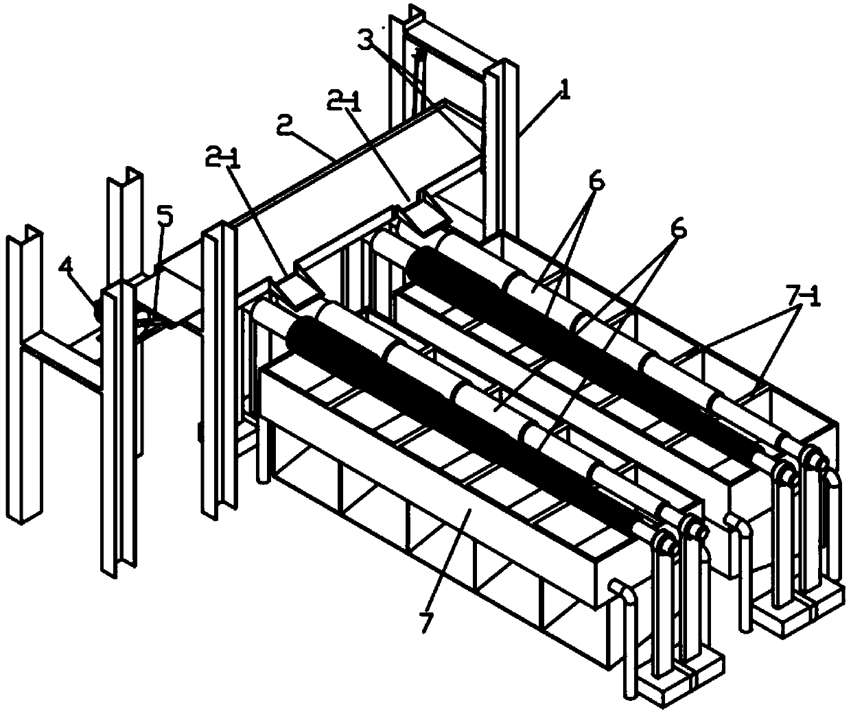
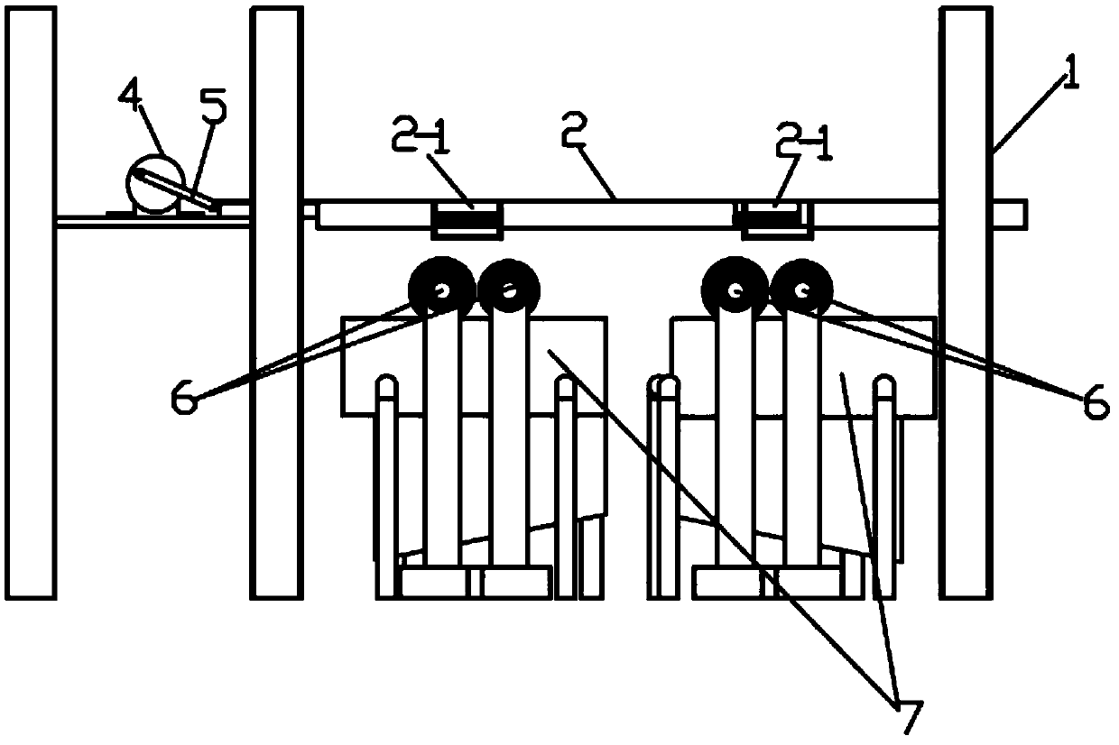
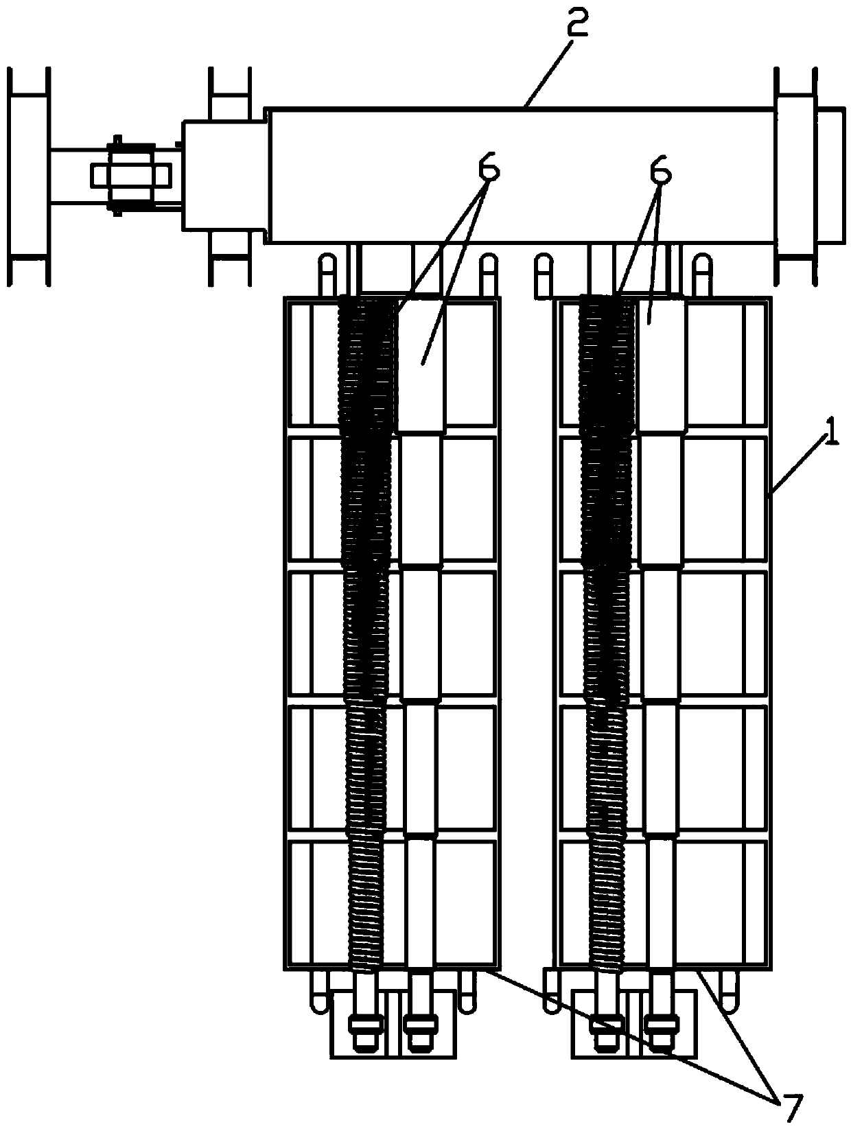
[0023] Depend on Figure 1-4 As can be seen from the illustrated embodiment, the present embodiment includes a frame 1, a peanut feeding device, a peanut grading device and a peanut collecting device, and the peanut feeding device includes a feeding trough 2, a boom 3 and a driving structure, and the lower end of the boom 3 Connect with the right end of feeding chute 2 through rotating shaft, the upper end of boom 3 is connected with frame 1 through rotating shaft, so that the right end of feeding chute 2 is hung on the frame, the driving structure includes feeding chute drive motor 4 and rocker Arm 5, feeding chute driving motor 4 are hinged with the left end of feeding chute 2 through rocker arm 5, so that feeding chute 2 swings left and right, and more than one discharge port 2-1 is provided on the rear side wall of feeding chute 2...


PUM


Abstract

The invention discloses a peanut grading machine and belongs to the technical field of peanut grading equipment. The peanut grading machine comprises a rack, a peanut feeding device, a peanut gradingdevice and peanut collection devices. The peanut feeding device comprises a feeding chute, suspension arms and a driving structure. The peanut grading device comprises a peanut grading channel and a peanut grading strip hole, wherein the peanut grading strip hole is formed in the lower end of the peanut grading channel. The peanut grading device specifically structurally comprises two grading rollers and a grading roller driving device, wherein the two grading rollers are arranged symmetrically in the left-right direction. The grading roller driving device drives the two grading rollers to rotate in opposite directions, so that inner side arc surfaces of the upper half parts of the two grading rollers rotate from inside to outside. A gap formed between the two grading rollers which are combined together serves as the peanut grading strip hole. The peanut grading strip hole is composed of peanut grading strip hole sections of different widths. Each peanut collection device is arranged at the lower end of the corresponding peanut grading strip hole section. The peanut grading machine has the advantages that grading is conducted precisely, the universality is great, and grading holesare not likely to be blocked.

Description

technical field [0001] The invention relates to the technical field of peanut grading equipment. Background technique [0002] Peanut grading mainly includes peanut pod grading and peanut kernel grading. At present, there are two common types of peanut grading equipment, vibrating screen peanut grading machine and drum type peanut grading machine, both of which have some problems in use. The vibrating sieve peanut grading machine utilizes sieve holes of appropriate size and shape to allow peanuts of different sizes and shapes to pass through the sieve holes to complete the classification through vibration. Existing problems: 1. When using a vibrating screen to classify peanut pods, small heads of peanuts often enter the sieve holes, and the big heads get stuck in the sieve holes and cannot pass through, and the more vibrating, the tighter the sieve holes are blocked, and it is not easy to block them. clean up. 2. When using a vibrating screen to classify peanut kernels, s...

Claims


Application Information

Patent Timeline
Patent Type & Authority Applications(China)
IPC IPC(8): B07B1/14B07B1/42B07B1/46
CPCB07B1/145B07B1/42B07B1/46
Inventor 郝建军张贺斌李建昌马志凯赵建国李浩张瑞青龙思放聂庆亮贾述飞
Owner HEBEI AGRICULTURAL UNIV.
Learn More