
Thrombus-removaldredging device for medical surgery

A dredging device and thrombus technology, applied in the direction of surgery, medical science, etc., can solve the problems of unfavorable small blood vessels, complicated equipment, thrombus removal, etc., and achieve the effect of improving continuity, reducing the lower limit of size, and realizing reciprocating utilization.

Pending Publication Date: 2019-04-16
邓一萍
View PDF8 Cites 2 Cited by
  • Summary
  • Abstract
  • Description
  • Claims
  • Application Information

AI Technical Summary

Problems solved by technology

[0003] Although there are some tools in the prior art that can be inserted into blood vessels to treat venous thrombosis minimally invasive surgery, at that time most of the tools used mechanical stripping, and the stripped fragments would flow with the blood instead of being excreted from the body. , which in turn increases the probability of reoccurrence of thrombus. In addition, because the position where blockage is likely to occur in the blood vessel is often a thinner blood vessel area, the existing resection tool has complex equipment and high cost due to the many operations that need to be performed. The structure of the control actuator is more, resulting in a larger volume, which is not conducive to thrombus removal in thin blood vessels

Method used


Image

  • Thrombus-removaldredging device for medical surgery
  • Thrombus-removaldredging device for medical surgery
  • Thrombus-removaldredging device for medical surgery

Examples


Embodiment 1

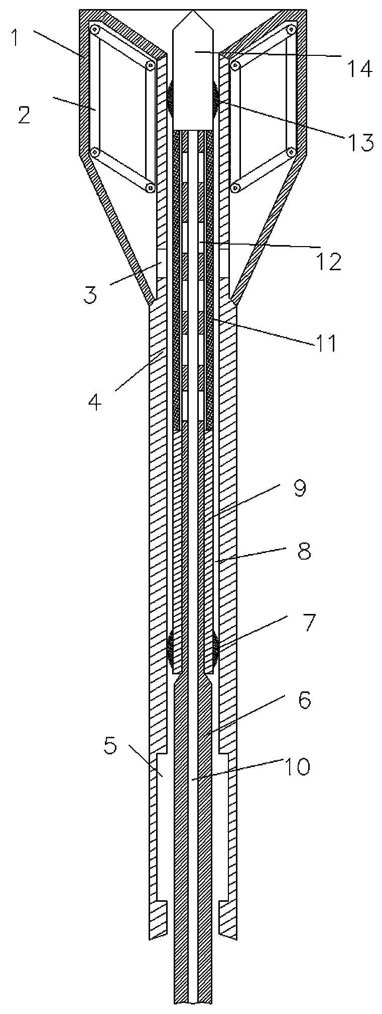
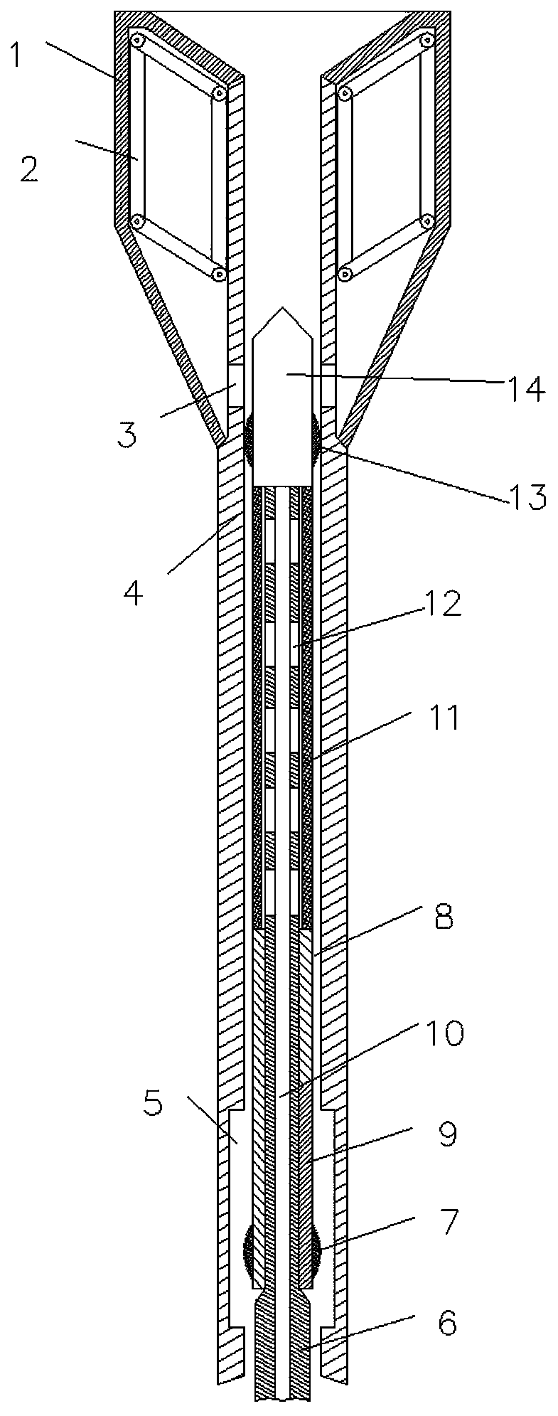
[0050] Such as Figure 1-4 As shown, a thrombus dredging device for medical operation of the present invention includes an outer sleeve 4, an inner sleeve 6 and a fluid passage. The inner sleeve 6 is coaxially arranged in the outer sleeve 4 and can be telescoped along its axial direction. In addition, the inner sleeve 6 can extend from the head of the outer sleeve 4 to puncture the thrombus; on the outer side of the head of the outer sleeve 4, a flexible sealing cover 1 and a support frame 2 are provided, and the support frame 2 is located in the flexible sealing cover 1 and used for radial Expand the flexible sealing cover 1; a first sealing portion 13 is provided between the inner and outer sleeves, and the outer sleeve 4 is provided with a pressure control hole 3 that communicates with the flexible sealing cover 1; the liquid passage is used to suck away the thrombus, and the liquid The channel can adjust the pressure in the flexible sealing cover 1 through the pressure cont...

Embodiment 2

[0053] Such as Figure 1-4 As shown, a thrombus dredging device used in medical operations of the present invention includes an outer sleeve 4, an inner sleeve 6 and a fluid passage. The inner sleeve 6 is coaxially arranged in the outer sleeve 4 and can be telescoped along its axial direction. And the inner sleeve 6 can extend from the head of the outer sleeve 4 to puncture the thrombus; on the outer side of the head of the outer sleeve 4, a flexible sealing cover 1 and a support frame 2 are provided, and the support frame 2 is located in the flexible sealing cover 1 and used for radial Expand the flexible sealing cover 1; a first sealing portion 13 is provided between the inner and outer sleeves, and the outer sleeve 4 is provided with a pressure control hole 3 that communicates with the flexible sealing cover 1; the liquid passage is used to suck away the thrombus, and the liquid The channel can adjust the pressure in the flexible sealing cover 1 through the pressure control ...

Embodiment 3

[0058] Based on the thrombus dredging device structure in embodiment 1, the blood vessel sealing method includes the following steps:

[0059] Step 1: Control the inner sleeve 6 to expand and contract along the axial direction of the outer sleeve 4 so that the sealing part is sealed between the inner and outer sleeves and the fluid passage is communicated with the space in the flexible sealing cover through the pressure control hole 3;

[0060] Step 2: Decrease the pressure in the liquid passage and close the flexible sealing cover along the radial direction of the outer sleeve 4;

[0061] Step 3: Synchronous movement of the inner and outer sleeve, so that the head of the outer sleeve 4 reaches the thrombus in the blood vessel;

[0062] Step 4: The pressure in the liquid passage is increased, and the support frame 2 pushes the flexible sealing cover to radially expand and fit the inner side wall of the blood vessel, so that the flexible sealing cover seals the blood vessel.


PUM


Abstract

The invention relates to a thrombus-removaldredging device for medical surgery and belongs to the field of medical tools and instruments, in particular to the field of thrombus-removaltools for medical surgery. The thrombus-removaldredging device comprises an outer cannula, an inner cannula and a liquid channel, wherein the inner cannula is coaxially arranged in the outer cannula, can axially telescope in the axial directionof the inner cannula and can extend out from the head portion of the outer cannula so as to puncture a thrombus; the outer side of the head portion of the outer cannula isprovided with a flexible sealing cover and a supporting frame, the supporting frame is located in the flexible sealing cover and used for radially propping the flexible sealing cover open; a first sealing portion is arranged between the inner cannulaand the outer cannula, and the outer cannula is provided with a pressure control hole communicated with the flexible sealing cover; the liquid channelis for sucking away the thrombus and can adjust the pressure in the flexible sealing cover through the pressure control hole to make the flexible sealing covercontractradially. For overcoming the shortcomings in the prior art, the structure is simplified, the lower limit of the size of the structure can be designed to be lower, the broken thrombus can be sucked away, and the probability can be reduced that the broken thrombus blocks the blood vessel again.

Description

Technical field [0001] The invention relates to a thrombus dredging device used in medical operations, belonging to the field of medical tools and instruments, in particular to the field of tools used for thrombus dredging for medical operations. Background technique [0002] Thrombus is a small piece formed by the blood flow on the surface of the exfoliated or repaired part of the blood vessel of the cardiovascular system. It is composed of insoluble fibrin, deposited platelets, accumulated white blood cells and trapped red blood cells. The scary thing about thrombosis is that it can cause local blockage, which can cause organ ischemia, hypoxia and failure. Thrombosis can appear in arteries in any part of the body. If it appears at the bifurcation of the cerebral blood vessel, it will cause cerebral infarction or cerebral embolism, while it may cause coronary heart disease if it appears at the coronary artery. These diseases may cause sudden death. Generally, thrombectomy sur...

Claims


Application Information

Patent Timeline
Patent Type & Authority Applications(China)
IPC IPC(8): A61B17/22
CPCA61B17/22A61B2017/22082A61B2017/22079A61B2017/22051
Inventor 邓一萍
Owner 邓一萍
Learn More