
Overhead flexible direct current power grid fault detection method based on current limiting reactor voltage difference

A technology for current limiting reactors and power grid faults, applied in fault locations, detecting faults according to conductor types, instruments, etc., can solve the problems of not being able to withstand transition resistance, anti-interference and identifying single-pole faults at the same time, and achieve strong anti-interference. ability, the effect of eliminating noise interference

Active Publication Date: 2019-04-12
HUAZHONG UNIV OF SCI & TECH
View PDF4 Cites 12 Cited by
  • Summary
  • Abstract
  • Description
  • Claims
  • Application Information

AI Technical Summary

Problems solved by technology

[0006] Aiming at the defects and improvement needs of the prior art, the present invention provides a fault detection method for overhead flexible DC power grids based on the voltage difference of current-limiting reactors, aiming to solve the problem that the existing fault detection methods for flexible DC grids cannot simultaneously withstand transition Problems with resistance, immunity to interference, and identifying single-pole faults

Method used


Image

  • Overhead flexible direct current power grid fault detection method based on current limiting reactor voltage difference
  • Overhead flexible direct current power grid fault detection method based on current limiting reactor voltage difference
  • Overhead flexible direct current power grid fault detection method based on current limiting reactor voltage difference

Examples


Embodiment Construction

[0041] In order to make the object, technical solution and advantages of the present invention clearer, the present invention will be further described in detail below in conjunction with the accompanying drawings and embodiments. It should be understood that the specific embodiments described here are only used to explain the present invention, not to limit the present invention. In addition, the technical features involved in the various embodiments of the present invention described below can be combined with each other as long as they do not constitute a conflict with each other.

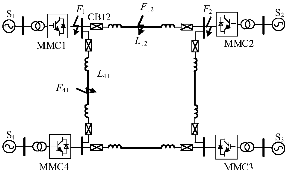
[0042] Before explaining the technical solution of the present invention in detail, a brief introduction is made to the relevant knowledge of the fault detection of the overhead flexible DC power grid. figure 1 The topological structure of an existing overhead flexible DC power grid is shown, and its sub-modules adopt a half-bridge structure. Since the half-bridge MMC does not have the ability t...


PUM


Abstract

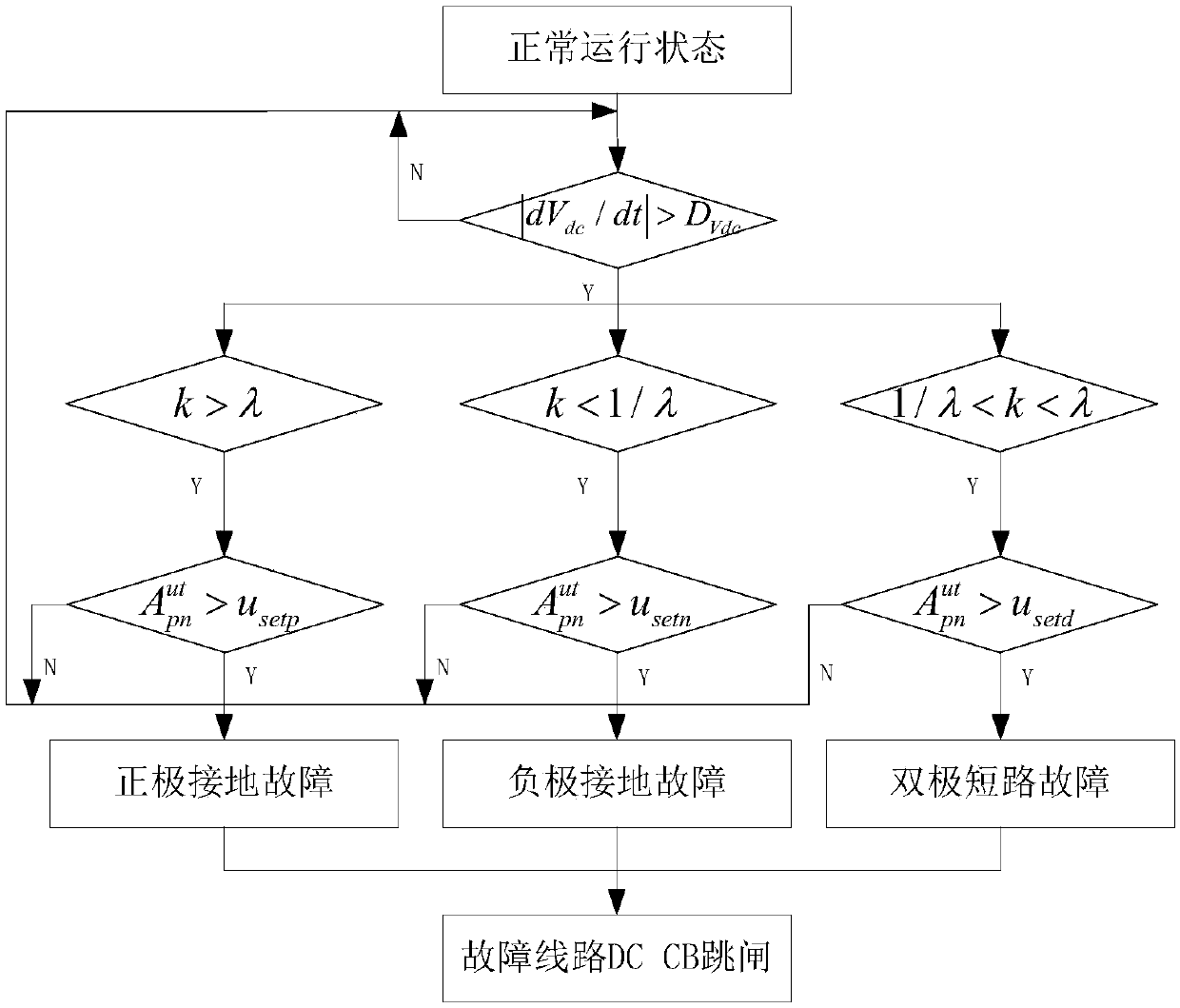
The invention discloses an overhead flexible direct current power grid fault detection method based on current limiting reactor voltage difference. The overhead flexible direct current power grid fault detection method based on the current limiting reactor voltage difference comprises the steps that (1) direct voltage change rates of each of direct current lines in a power grid are continuously monitored, and when the direct voltage change rates are greater than a preset first threshold value, turning into a step (4) is carried out; (2) at one ends of the direct current lines, voltage time products of positive pole current limiting reactors and negative pole current limiting reactors within a target time period are correspondingly obtained and specific values are determined so as to carryout fault pole selection; (3) the sum of the voltage time products of the positive pole current limiting reactors and the negative pole current limiting reactors is obtained, and a second threshold value corresponding to a fault type is obtained, if the sum of the voltage time products is greater than the second threshold value, an occurred fault is determined as a fault inside a zone; if not, theoccurred fault is determined as a fault outside the zone or no fault; and (4) at the two ends of the direct current lines, the step(2)-step(3) are correspondingly carried out to achieve the fault detection. The overhead flexible direct current power grid fault detection method based on the current limiting reactor voltage difference has a high tolerating transition resistance capacity and a highcapacity of resisting disturbance, and can identify various fault types.

Description

technical field [0001] The invention belongs to the field of flexible DC power grids, and more specifically relates to a fault detection method for overhead flexible DC power grids based on voltage differences of current-limiting reactors. Background technique [0002] The DC transmission technology based on Modular Multilevel Converter (MMC) is widely used in new energy power generation, There are broad application scenarios in asynchronous interconnection, urban power grid capacity expansion, power supply to passive systems, and connection to weak AC power grids. In order to further improve the operation flexibility and power supply reliability, the multi-terminal flexible DC grid based on MMC has become one of the development trends of the future smart grid. [0003] Considering the transmission distance, voltage level and cost, overhead line transmission is one of the main ways of large-scale power transmission. The working environment of overhead lines is harsh, and t...

Claims


Application Information

Patent Timeline
Patent Type & Authority Applications(China)
IPC IPC(8): G01R31/08
CPCG01R31/086G01R31/088Y04S10/52
Inventor 杨赛昭向往文劲宇
Owner HUAZHONG UNIV OF SCI & TECH
Learn More