
Protective cover for photoelectric tracking-pointing equipment

A protective cover and equipment technology, applied in the field of protective cover, can solve the problems that the opening and closing of the protective cover cannot be realized automatically, the operation time is long, and the operation is inconvenient, etc., and it is beneficial to rainproof, simple in design and clear in principle Effect

Inactive Publication Date: 2019-04-12
BEIJING INST OF ELECTRONICS SYST ENG
View PDF6 Cites 1 Cited by
  • Summary
  • Abstract
  • Description
  • Claims
  • Application Information

AI Technical Summary

Problems solved by technology

[0003] At present, the protective cover of photoelectric tracking and aiming equipment is generally disassembled and transported manually, which cannot realize the automation of opening and closing of the protective cover.
Therefore, when the photoelectric tracking and aiming equipment is large in size or installed in a high position, it will bring inconvenience to the operation of the personnel and take a long time to operate.

Method used


Image

  • Protective cover for photoelectric tracking-pointing equipment
  • Protective cover for photoelectric tracking-pointing equipment
  • Protective cover for photoelectric tracking-pointing equipment

Examples


Embodiment Construction

[0025] In order to illustrate the present invention more clearly, the present invention will be further described below in conjunction with preferred embodiments and accompanying drawings. Similar parts in the figures are denoted by the same reference numerals. Those skilled in the art should understand that the content specifically described below is illustrative rather than restrictive, and should not limit the protection scope of the present invention.

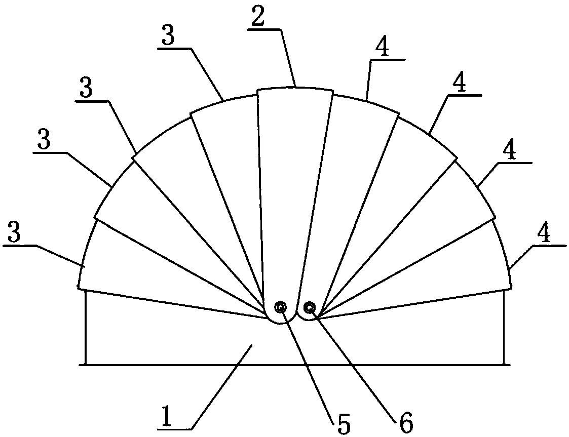
[0026] figure 1 Show the front view of the protective cover for the photoelectric tracking and aiming equipment proposed by the embodiment of the present invention, as figure 1 As shown, it includes a bottom frame and active protection flaps, at least one first passive protection flap and at least one second passive protection flap arranged on the bottom frame.

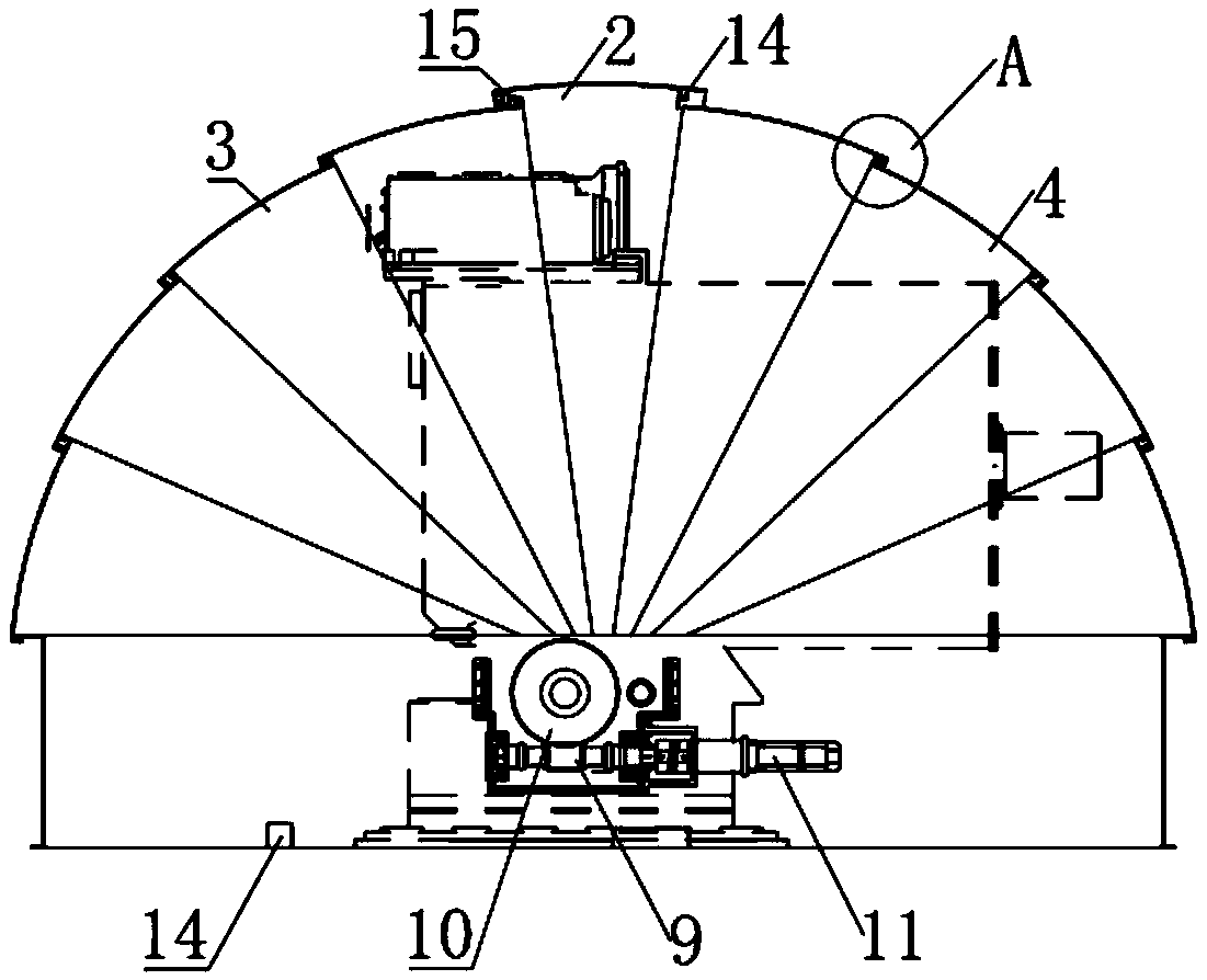
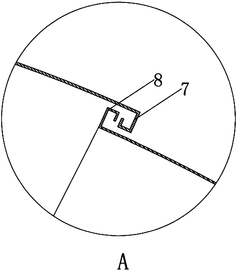
[0027] Specifically, according to Figure 1-Figure 4 It can be seen that the bottom frame is mainly used to carry the photoelectric tracking and sighting equipm...


PUM


Abstract

The invention discloses a protective cover for photoelectric tracking-pointing equipment. The protective cover comprises a bottom frame, a driving protective piece, first driven protective pieces andsecond driven protective pieces, wherein the driving protective piece, the first driven protective pieces and the second driven protective pieces are arranged on the bottom frame; the driving protective piece and the bottoms of the first driven protective pieces are hinged to a first hinged position, the bottoms of the second driven protective pieces are hinged to a second hinged position, a driving bending hooked claw is arranged at the side edge, close to the first driven protective pieces, of the driving protective piece, and a driven bending hooked claw is arranged at the side edges, closeto the driving protective piece, of the first driven protective pieces; and the driving protective piece and the first driven protective pieces are in hooked-claw connection through cooperation between the driving bending hooked claw and the driven bending hooked claw, and the bottom frame is provided with a driving device used for simultaneously driving the driving protective piece to rotate anddriving the second driven protective pieces to rotate in the direction opposite to the rotating direction of the driving protective piece. According to the protective cover, the protective cover canbe opened and closed automatically.

Description

technical field [0001] The invention relates to the field of optoelectronic technology, in particular to a protective cover for optoelectronic tracking and aiming equipment. Background technique [0002] Photoelectric tracking and aiming equipment is a kind of photoelectric servo tracking equipment widely used in military and civilian products. It usually consists of a base, a servo turret, and a lens. In order to realize the target tracking and aiming function, the photoelectric tracking and aiming equipment usually has a certain field of view requirement (for example, the pitch angle is not lower than a certain angle). [0003] At present, the protective cover of photoelectric tracking and aiming equipment is generally disassembled and transported manually, which cannot realize the automation of opening and closing the protective cover. Therefore, when the photoelectric tracking and sighting equipment is large in size or installed in a high position, it will bring inconve...

Claims


Application Information

Patent Timeline
Patent Type & Authority Applications(China)
IPC IPC(8): G01D11/24G01D11/26F16H1/16
CPCF16H1/16G01D11/24G01D11/26
Inventor 何蕾马捷郝键
Owner BEIJING INST OF ELECTRONICS SYST ENG
Learn More