
Dry low-emission burner

A low-emission, burner technology, used in combustion chambers, combustion methods, combustion equipment, etc., can solve the problems of no grading and zoning of fuel, reduction of pollutant emissions, and difficulty in meeting pollutant emission standards, and to expand the range of operating conditions. , Control the effect of tempering

Active Publication Date: 2019-04-12
AECC SHENYANG ENGINE RES INST
View PDF11 Cites 5 Cited by
  • Summary
  • Abstract
  • Description
  • Claims
  • Application Information

AI Technical Summary

Problems solved by technology

[0003] (1) There is no classification and division of fuel, which makes it difficult to design the transitional working conditions of the burner, and cannot take into account the combustion stability of low working conditions and the pollutant emission indicators of high working conditions;
[0004] (2) Due to the diffusion combustion mode, sufficient mixing of fuel and air cannot be achieved, which is not conducive to the reduction of pollutant emissions, making it difficult to meet the standards for pollutant emission indicators;
[0005] (3) The burner of this design form is prone to problems such as thermoacoustic vibration and flameout in the actual application process

Method used


Image

  • Dry low-emission burner
  • Dry low-emission burner

Examples


Embodiment Construction

[0038] The application will be further described in detail below in conjunction with the accompanying drawings and embodiments. It should be understood that the specific embodiments described here are only used to explain the related application, not to limit the application. In addition, it should be noted that, for ease of description, only parts relevant to the present application are shown in the drawings.

[0039] It should be noted that, in the case of no conflict, the embodiments in the present application and the features in the embodiments can be combined with each other. The present application will be described in detail below with reference to the accompanying drawings and embodiments.

[0040] It should be noted that in the description of this application, the terms "center", "upper", "lower", "left", "right", "vertical", "horizontal", "inner", "outer", etc. The terms of the indicated direction or positional relationship are based on the direction or positional ...


PUM


Abstract

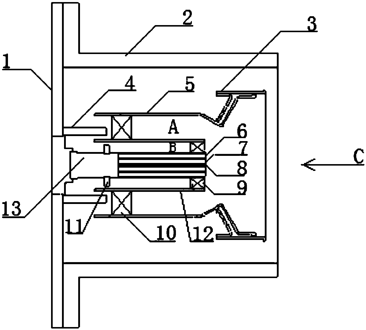
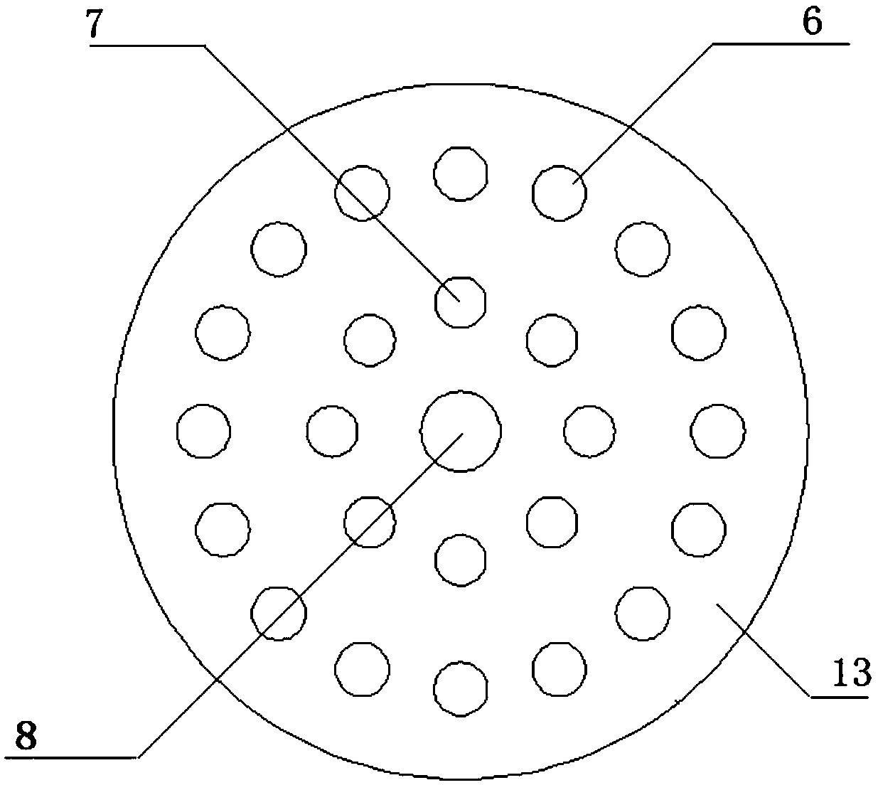
The invention belongs to the technical field of burner design, and particularly relates to a dry low-emission burner. The dry low-emission burner includes a venturi tube, a premixing outdoor cylinder,a premixing indoor cylinder, a nozzle body, a main combustion premixing spraying rod and a precombustion premixing spraying rod, wherein the outlet end of the premixing outdoor cylinder is connectedwith the inlet end of the venturi tube, the premixing indoor cylinder is arranged on the inner side of the premixing outdoor cylinder to form a main combustion level premixing channel with the premixing outdoor cylinder, and the nozzle body is arranged on the inner side of the premixing indoor cylinder, and a precombustion premixing level channel is formed between the nozzle body and the premixingindoor cylinder; the nozzle body is internally provided with a precombustion diffusion channel, the precombustion diffusion channel penetrates through the nozzle body in the axial direction, the end,close to the venturi tube, of the precombustion diffusion channel is provided with a precombustion diffusion nozzle hole, and the other end, close to the venturi tube, of the precombustion diffusionchannel communicates with a fuel source; and the inlet end of the main combustion premixing spraying rod communicates with the fuel source, the outlet end is arranged at the inlet end of the main combustion premixing level channel, the outlet end of the main combustion premixing spraying rod is provided with a main combustion premixing nozzle hole, the inlet end of the precombustion premixing spraying rod communicates with the fuel source, the outlet end is arranged at the inlet end of the precombustion premixing level channel, and the outlet end of the precombustion premixing spraying rod isprovided with a precombustion premixing nozzle hole.

Description

technical field [0001] The application belongs to the technical field of burner design, and in particular relates to a dry low-emission burner. Background technique [0002] The dry low emission technology of the gas turbine combustor is relative to the water injection / steam technology, and it is an important technical means to reduce the pollutant emission of the gas turbine. At present, dry low-emission burners mostly adopt the fuel-lean premixed combustion mode, and the fuel is not graded. In order to ensure the stability of combustion, a certain proportion of diffusion combustion fuel is reserved in the center of the burner. This technical solution has the following defects: [0003] (1) There is no classification and division of fuel, which makes it difficult to design the transitional working conditions of the burner, and cannot take into account the combustion stability of low working conditions and the pollutant emission indicators of high working conditions; [000...

Claims


Application Information

Patent Timeline
Patent Type & Authority Applications(China)
IPC IPC(8): F23R3/38F23R3/28
CPCF23R3/286F23R3/38
Inventor 贾春燕李孝堂马宏宇齐兵张善军赵凯岚陈明禄
Owner AECC SHENYANG ENGINE RES INST
Learn More