Gas boiler and tail gas cooling and water outlet seal method thereof

A gas-fired boiler and water outlet technology, applied in the field of boilers, can solve the problems of unutilized exhaust heat, leakage of the water outlet, inability to deal with carbon monoxide in the exhaust gas, etc., and achieves the effect of increasing heat, convenient plugging, and increasing heat exchange time.

Active Publication Date: 2019-04-12
浙江云作工业设计有限公司
View PDF4 Cites 0 Cited by
  • Summary
  • Abstract
  • Description
  • Claims
  • Application Information

AI Technical Summary

Problems solved by technology

[0004] The first object of the present invention is to provide a gas boiler that can use exhaust gas to heat gas fuel to realize the utilization of exhaust heat, which solves the problem that the exhaust heat of existing gas boilers is not utilized
[0005] The second object of the present invention aims at further providing a gas-fired boiler capable of removing carbon monoxide in the tail gas on the basis of the first object, which solves the problem that the existing gas-fired boilers cannot handle the carbon monoxide in the tail gas
[0006] The third purpose of the present invention is to further provide a gas-fired boiler that can plug the leak without sending it to the outlet pipe when the water outlet leaks, which solves the need to loosen the outlet pipe when the water outlet leaks in the existing gas-fired boiler to be able to reseal the problem

Method used


Image

  • Gas boiler and tail gas cooling and water outlet seal method thereof
  • Gas boiler and tail gas cooling and water outlet seal method thereof
  • Gas boiler and tail gas cooling and water outlet seal method thereof

Examples


Embodiment 1

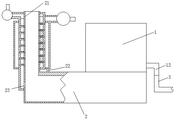
[0027] Embodiment one, see figure 1 and figure 2 , including a water tank 1 and a combustion furnace 2 for heating water in the water tank. The water tank 1 is provided with a water outlet 12 opening downward. The water outlet is sealed and connected with an outlet pipe 3 .

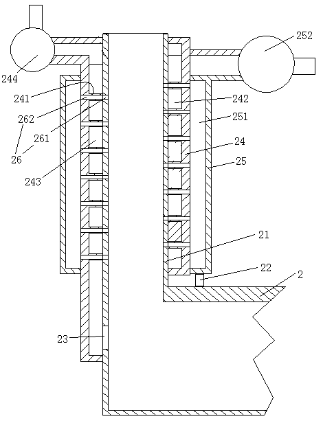
[0028] The combustion furnace 2 is provided with a flue gas discharge pipe 21 , an air inlet 22 and a gas inlet 23 . The outer casing of the flue gas discharge pipe is provided with an inner casing 24 . An outer sleeve 25 is provided on the outer sleeve of the inner sleeve. An inner air chamber 241 is formed between the inner casing and the exhaust gas discharge pipe. The inner air chamber is provided with a spiral piece 242 whose centerline is the centerline of the flue gas discharge pipe. The spiral piece forms a spiral fuel flow channel 243 in the inner air chamber. One end of the gas channel is connected with the gas inlet, and the other end is connected with the outlet of the gas pump 244 . ...

Embodiment 2

[0030] Embodiment two, the difference with embodiment one is:

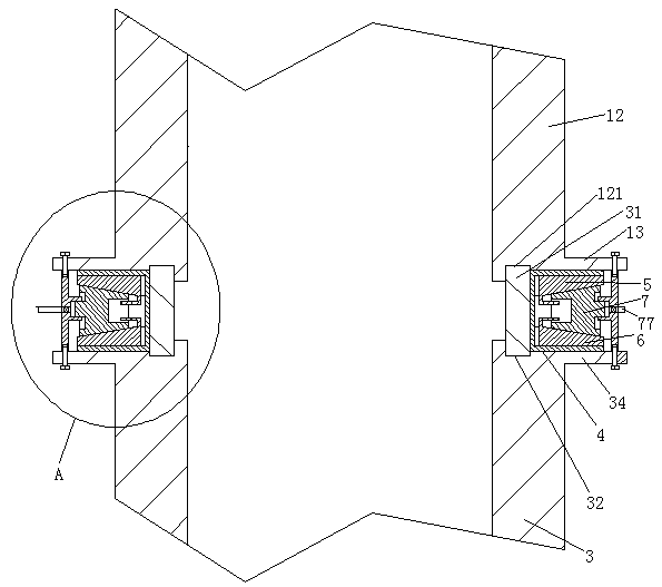
[0031] see image 3 and Figure 4 , also includes a limit ring 31. A water outlet limiting ring groove 121 extending along the circumference of the water outlet is provided on the lower end surface of the water outlet. The upper end surface of the water outlet pipe is provided with a water outlet pipe portion limiting ring groove 32 extending along the circumference of the water outlet pipe. The upper end of the limit ring is set in the limit ring groove of the water outlet part, and the lower end is set in the limit ring groove of the water outlet pipe part. An installation groove 33 extending along the circumference of the water outlet is formed between the water outlet, the limiting ring and the water outlet pipe. A sealing ring 4 is sleeved on the limit ring. The sealing ring includes an upper sealing side wall 41 , a connecting wall 42 and a lower sealing side wall 43 distributed sequentially from top to...


PUM


Abstract

The invention discloses a gas boiler and a tail gas cooling and water outlet seal method thereof. The gas boiler comprises a water tank and a combustion furnace for heating water in the water tank, asmoke discharge pipe, an air inlet and a gas inlet are formed in the combustion furnace, an inner casing pipe is arranged outside the smoke discharge pipe in a sleeving manner, an outer casing pipe isarranged outside the inner casing pipe in a sleeving manner, an inner air chamber is arranged between the inner casing pipe and the tail gas discharge pipe, a spiral piece with the center line of thesmoke discharge pipe as the centre line is arranged in the inner air chamber, the spiral piece forms a spiral fuel runner in the inner air chamber, one end of the gas channel and the gas inlet are connected together, the other end of the gas channel is connected with an outlet of an air pump, the part, in the inner casing pipe, of the smoke discharge pipe is made of a heat conduction material, anouter air chamber is arranged between the outer casing pipe and the inner casing pipe, one end of the outer air chamber is connected with the air inlet, and the other end of the outer air chamber isconnected with an outlet of the air blower. The gas boiler has the advantage that the tail gas can be used for heating gas fuel to achieve tail gas heat use, and the problem that tail gas heat of an existing gas boiler is not used is solved.

Description

technical field [0001] The invention relates to a boiler, in particular to a gas-fired boiler and its tail gas heat dissipation and water outlet sealing method. Background technique [0002] Boilers used to heat hot water are divided into electric boilers, coal-fired boilers, and gas-fired boilers according to different heat sources (the fuel fed to water is heated by gas fuel combustion. The basic structure of a gas-fired boiler includes a water tank and a combustion furnace that heats the water in the water tank The combustion furnace is provided with a flue gas discharge pipe, an air inlet and a gas inlet, the water tank is provided with a water outlet, and the water outlet is sealed and connected with the water outlet pipe to discharge the water in the water tank. [0003] The existing gas-fired boilers have the following disadvantages: when the exhaust gas contains carbon monoxide due to insufficient combustion during the combustion process, the carbon monoxide cannot b...

Claims


Application Information

Patent Timeline
Patent Type & Authority Applications(China)
IPC IPC(8): F23J15/06F23L15/04F23D14/66F23G7/06F16J15/06
CPCF16J15/06F23D14/66F23G7/06F23J15/06F23L15/04Y02E20/34
Inventor 徐瑾
Owner 浙江云作工业设计有限公司
Why Eureka
Try Eureka