
Fodder mixing device for livestock rearing

A mixing device and feed technology, applied in feed, mixer, mixing method, etc., can solve the problems of nutrient loss in feed additives, achieve the effect of improving mixing effect, avoiding blockage, and improving breeding quality

Inactive Publication Date: 2019-04-12
王洪军
View PDF1 Cites 2 Cited by
  • Summary
  • Abstract
  • Description
  • Claims
  • Application Information

AI Technical Summary

Problems solved by technology

However, in the process of mixing green fodder and feed additives in this device, due to the high moisture content of green fodder, it is easy to dissolve the feed additives, resulting in the loss of nutrients in the feed additives.

Method used


Image

  • Fodder mixing device for livestock rearing
  • Fodder mixing device for livestock rearing
  • Fodder mixing device for livestock rearing

Examples


Embodiment 1

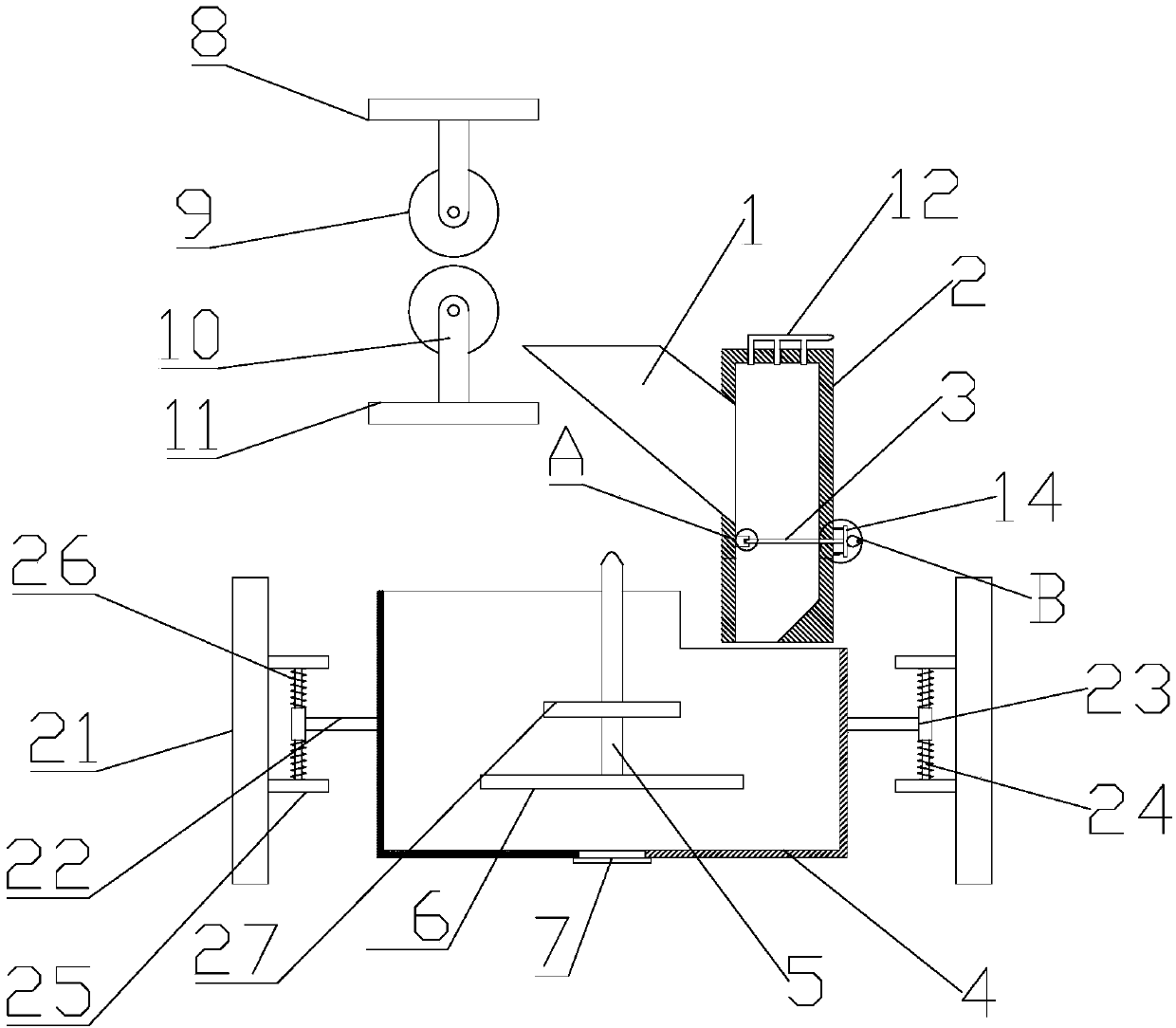
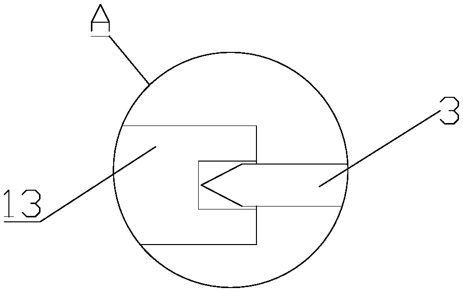
[0018] see figure 1 and figure 2 , a feed mixing device for animal husbandry, comprising a hopper 1, a cutting box 2, a cutting knife 3, a mixing box 4, a mixing shaft 5, a mixing arm 6, a discharge port 7 and a water squeezing mechanism 8, and the water squeezing mechanism 8 is right The hopper 1 is arranged on the side, and the cutting box 2 is arranged on the right side of the hopper 1. The hopper 1 communicates with the cutting box 2, and the cutting knife 3 is installed inside the cutting box 2. The mixing box 4 is arranged below the cutting box 2, the mixing shaft 5 is arranged in the mixing box 4, the mixing arm 6 is welded and fixed on the bottom of the mixing shaft 5, and the bottom of the mixing box 4 is provided with a The discharge port 7 is described; the water squeezing mechanism 8 includes a squeeze roller 9, a roller mounting frame 10 and a top plate 11, and the number of the squeeze rollers 9 is two, and the two squeeze rollers 9 are placed up and down, and ...

Embodiment 2

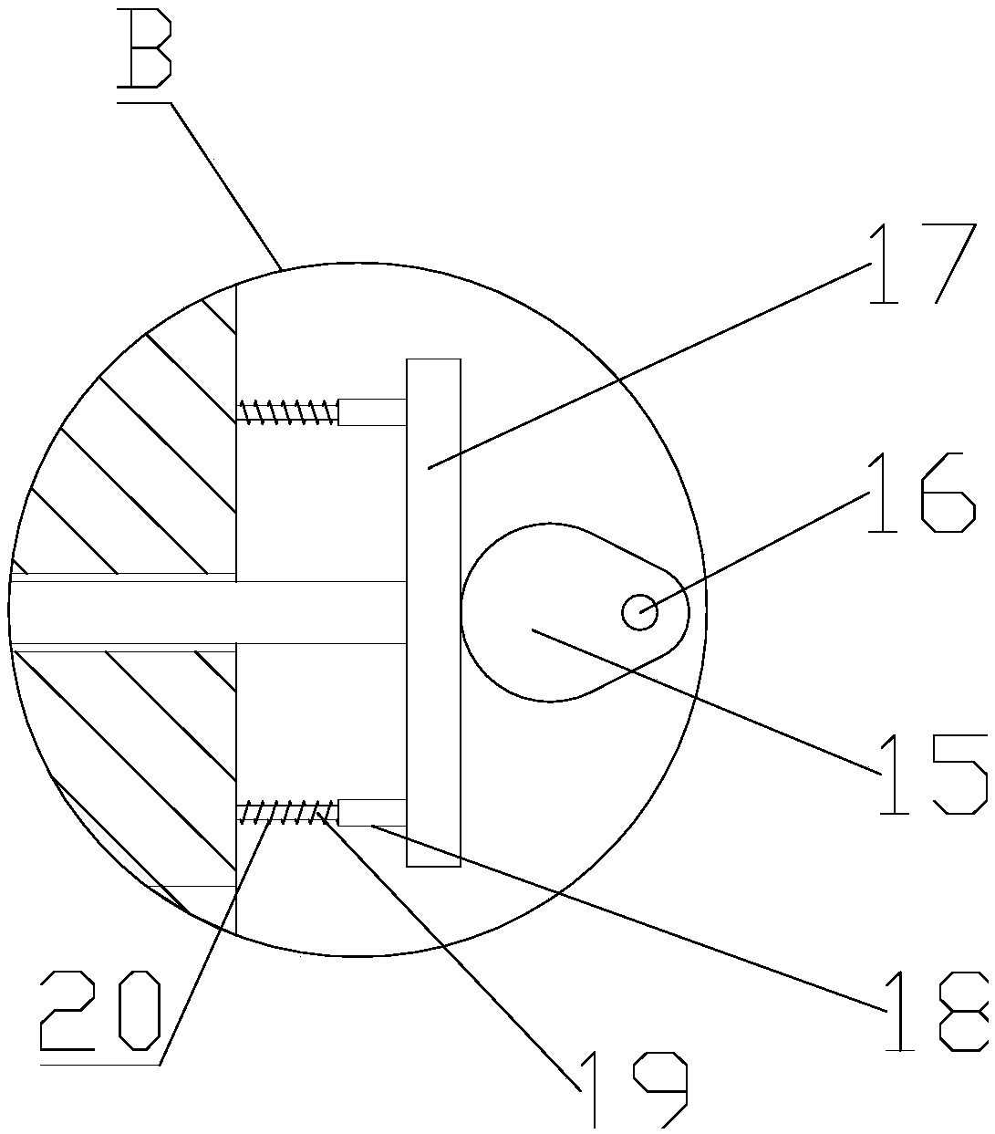
[0020] see figure 1 and image 3 , the pushing mechanism 14 includes a cam 15, a camshaft 16, a push plate 17, a sleeve 18, a slide bar 19 and a spring A20, and the cam 15 is welded and fixed on the camshaft 16, and the cam 15 and the The push plate 17 is in close contact with the left end surface of the push plate 17 and the right end of the sleeve 18 is welded and fixed, and a slide bar 19 is slidably installed in the sleeve 18, and the left end of the slide bar 19 is welded and fixed on the cut-off plate. On the outer wall of the box 2, the slide bar 19 is also covered with a spring A20.

[0021] The working principle of the present invention is: the green fodder passes between the upper and lower two squeeze rollers 9, and is extruded by the upper and lower two squeeze rollers 9, thereby playing the technical effect of fully squeezing water; the green fodder through squeezing water enters the described cutting box 2 Inside, the top of the cutting box 2 is provided with a...


PUM


Abstract

The invention relates to the technical field of fodder processing equipment for livestock rearing, in particular to a fodder mixing device for livestock rearing. The fodder mixing device comprises a hopper, a cutting box, a cutting knife, a mixing box, a mixing shaft, a mixing arm, an unloading port and a water squeezing mechanism; the water squeezing mechanism comprises two squeezing rollers, roller mounting shelves and roofs, the two squeezing rollers are placed up and down and rotatably mounted on the upper and lower roller mounting shelves respectively, and the upper and lower roller mounting shelves are fixed to the upper and lower roofs respectively through bolts; the right end of the cutting knife extends out of the cutting box and is in transmission connection with a pushing mechanism. The fodder mixing device is simple in structure and low in production cost, silage can be effectively mixed with other fodder additives after being subjected to water squeezing, nutritional ingredients in the fodder are effectively reserved, and the fodder mixing device is very important in improving the rearing quality and lowering the breeding cost.

Description

technical field [0001] The invention relates to the technical field of livestock feed processing equipment, in particular to a livestock feed mixing device. Background technique [0002] In the process of animal husbandry, feed is the most important part that determines the cost of breeding. The preparation of feed also determines the growth rate of livestock. In order to ensure the nutritional balance of livestock and reduce the cost of feed, green feed is usually used for feeding livestock. Green fodder refers to the fresh stems and leaves of plants that can be used as feed. It is named for its rich chlorophyll. However, during the use of green feed, since the green feed will be fermented during storage, a large amount of water will be produced, so the green feed needs to be drained before feeding. [0003] Chinese patent (notification number: CN204380551U, announcement date: 2015.06.10) discloses a feed mixer. The mixer includes a transmission device, a rotor assembly a...

Claims


Application Information

Patent Timeline
Patent Type & Authority Applications(China)
IPC IPC(8): B01F13/10B01F11/00B01F3/20A23N17/00B01F23/70
CPCA23N17/007B01F23/70B01F31/56B01F33/80B01F33/83612B01F2101/18
Inventor 王洪军
Owner 王洪军
Learn More