
Buffer device

A technology of buffer device and cylinder, which is used in projectiles, self-propelled projectiles, offensive equipment, etc., can solve the requirements of local structural strength and rigidity of satellite connection points and high concentrated force diffusion, and the work of pyrotechnic separation nut has large impact and influence. Problems such as the use of instruments and equipment, to achieve the effect of less protruding payload structure, lightweight, and small space requirements

Active Publication Date: 2019-04-09
SHANGHAI AEROSPACE SYST ENG INST
View PDF6 Cites 0 Cited by
  • Summary
  • Abstract
  • Description
  • Claims
  • Application Information

AI Technical Summary

Problems solved by technology

However, the working impact of the pyrotechnic separation nut in this scheme is relatively large, which has a great impact on the payload, and even affects the functions of some instruments and equipment on the payload. It is also contradictory to the impact environment requirements of the increasingly high payload.
Moreover, when the payload is launched into orbit through the delivery system, it needs to experience a relatively harsh vibration environment. Generally, it is necessary to take additional shock absorption measures for the sensitive components of the payload, and the weight gain is more obvious.
In addition, the point connection method causes the load transfer between the satellite and the rocket to be a concentrated force load, which has high requirements for the strength and stiffness of the local structure of the satellite connection point and the diffusion of concentrated force

Method used


Image

  • Buffer device
  • Buffer device

Examples


Embodiment 1

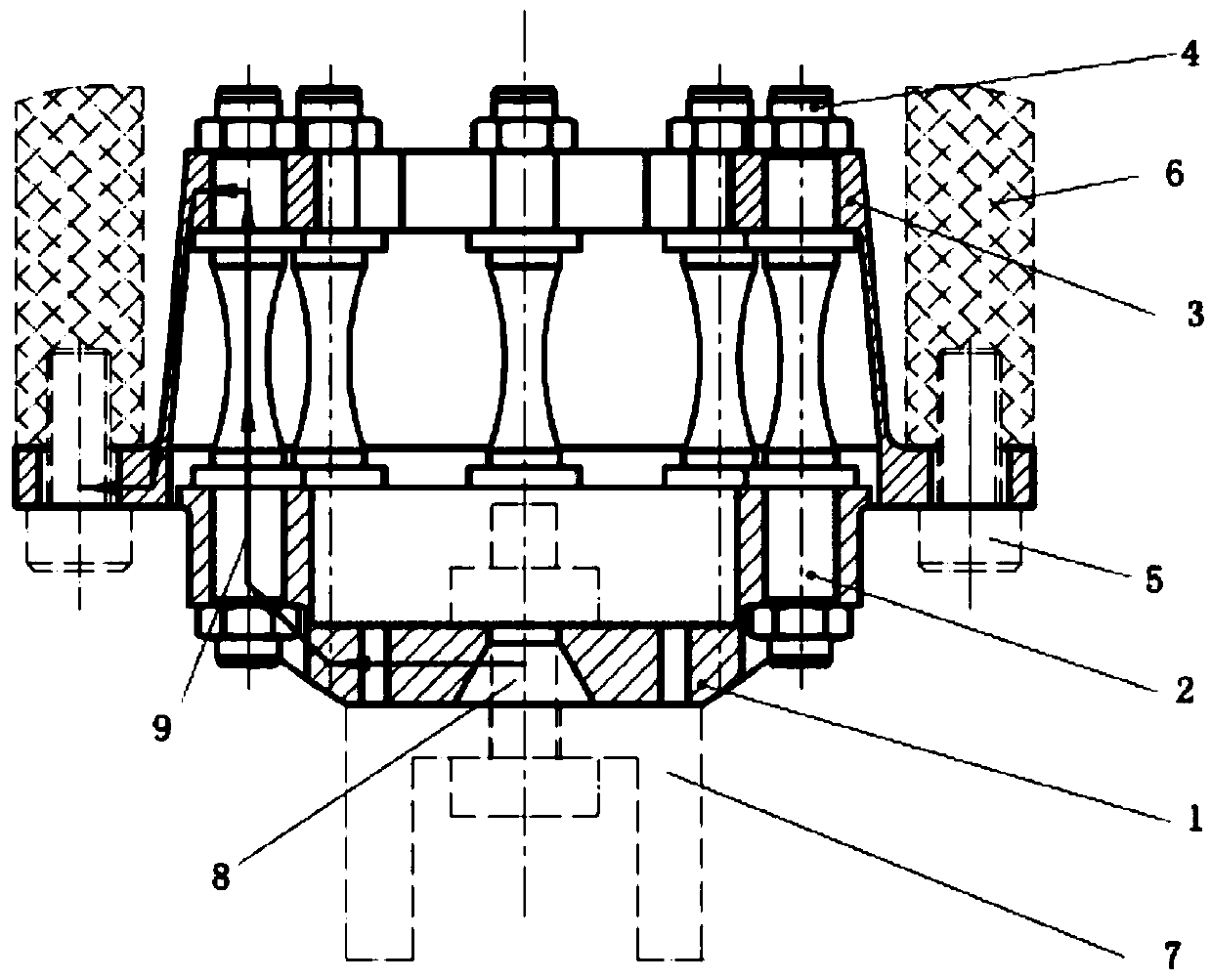
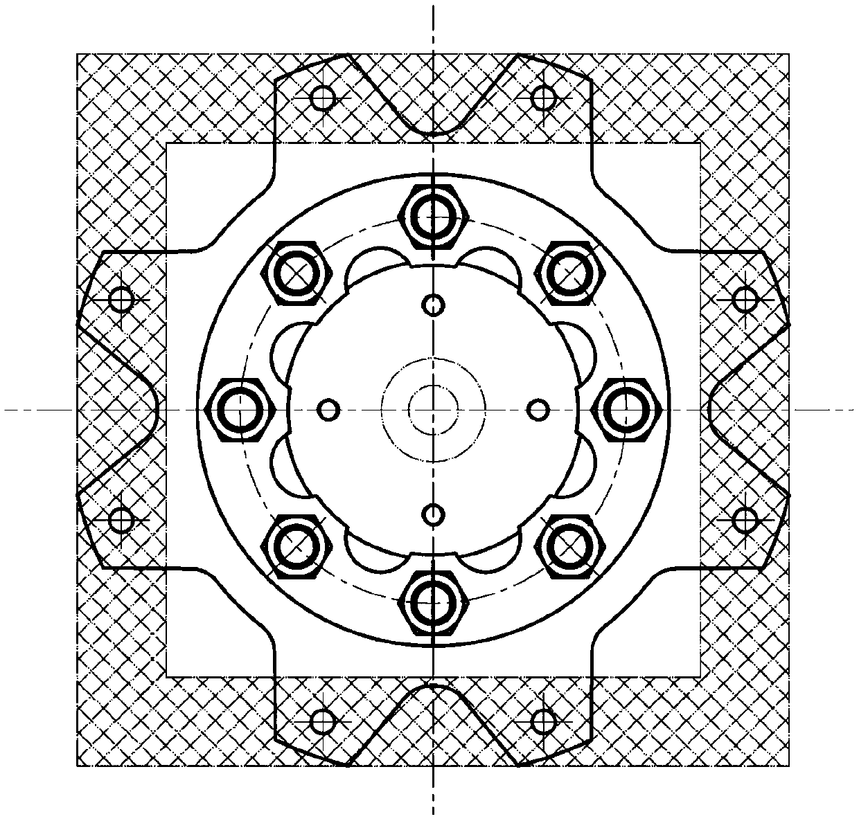
[0024] The present invention provides a buffer device, comprising: a flange 1, a stud bolt 2, a buffer cap 3 and a fastener 4, a through hole is provided in the center of the flange 1, and the through hole includes superimposed conical holes and cylindrical holes, used to connect the carrying system connection structure 7, around the circumference are provided with a number of screw holes, the distance between the screw holes and the center of the flange 1 is equal; the unilateral section of the buffer cap 3 is Z-shaped, the upper end The flange is provided with cylindrical through holes that match the size and number of screw holes on the flange around the central axis, and the positions correspond to the cylindrical through holes. The flange flanges are 8 trapezoidal lugs, and the trapezoidal lugs are provided with screw holes, which are connected to the payload connection structure 6 through the connecting bolt 5; the two ends of the stud bolt 2 are threaded cylindrical stru...

Embodiment 2

[0028] The difference between this embodiment and embodiment 1 is:

[0029] The stud bolt 2 is a cylindrical structure with threads at both ends, and the stud bolt is provided with a limit protrusion at a certain distance from the two ends, which cooperates with the fastener 4 to jointly limit and fix the flange 1 and buffer cap 3.

[0030] Apart from this, other aspects of this embodiment are the same as those of Embodiment 1, and are not repeated here.


PUM


Abstract

The invention discloses a buffer device which comprises a flange plate, double-end bolts, a buffer cap and fastening parts. A through hole is formed in the center of the flange plate, and multiple screw holes are formed around the flange plate, wherein the distance between the screw holes and the center is equal. The unilateral section of the buffer cap is in a Z shape, cylindrical through holes matched with the screw holes in the flange plate are formed in a flange at the upper end around the center axis, a middle transition segment is of a thin-wall structure, and flange turnup edges are arranged at the lower end and used for being fixed with an effective load connecting structure. Each double-end bolt is of a cylindrical structure with threads arranged at the two ends, and the cylindrical structures at the two ends are inserted into the screw holes of the flange plate and screw holes of the buffer cap and achieve cooperation and fixing through the fastening parts. The necessity of the buffer device with the functions of impact attenuation, vibration buffer and concentrated force diffusion is sufficient, and the effective buffer function can be achieved during equipment connecting or fixing.

Description

technical field [0001] The invention relates to the field of mechanical structure connection, in particular to a buffer device applied to the connection and separation position of a payload and a carrying system Background technique [0002] At present, the point-type device based on the pyrotechnic separation nut has mature technology and high reliability, and has been widely used in the connection and separation between the payload and the delivery system. However, in this scheme, the working impact of the pyrotechnic separation nut is relatively large, which has a great impact on the payload, and even affects the use function of some instruments and equipment on the payload. It also contradicts the impact environment requirements of the increasingly high payload. Moreover, when the payload is launched into the orbit through the delivery system, the vibration environment to be experienced is relatively harsh. Generally, additional shock absorption measures are required for...

Claims


Application Information

Patent Timeline
Patent Type & Authority Applications(China)
IPC IPC(8): F42B15/36
CPCF42B15/36
Inventor 李新宽秦震张醒郑权王金童赵学成冯淑红
Owner SHANGHAI AEROSPACE SYST ENG INST
Learn More