Tunnel vacuum furnace based on veneer backflow

A vacuum furnace and tunnel technology, applied in the field of product drying, can solve the problems of complex loading and unloading modules, high operation and maintenance costs, and easy occurrence of air leakage, so as to save the overall occupied space, facilitate the loading and unloading method, and eliminate air leakage. the effect of risk

Inactive Publication Date: 2019-04-09
CHANGZHOU DACHENG VACUUM TECH CO LTD
View PDF0 Cites 5 Cited by
  • Summary
  • Abstract
  • Description
  • Claims
  • Application Information

AI Technical Summary

Problems solved by technology

The single-body furnace requires a separate drying room, which has high operation and maintenance costs, low production capacity, and a large floor space; the vacuum tunnel furnace has high efficiency and does not require a separate drying room, but it uses a trolley backflow method and occupies a small area. Relatively large; at the same time, the electric box is controlled to move with the trolley, and the air from the outside of the cavity enters the electric box of the trolley inside the cavity for cooling, which is prone to air leakage; and the loading and unloading module is more complicated and costly

Method used


Image

  • Tunnel vacuum furnace based on veneer backflow
  • Tunnel vacuum furnace based on veneer backflow
  • Tunnel vacuum furnace based on veneer backflow

Examples


Embodiment Construction

[0026] The specific embodiments of the present invention will be further described below in conjunction with the accompanying drawings. It should be noted here that the descriptions of these embodiments are used to help understand the present invention, but are not intended to limit the present invention. In addition, the technical features involved in the embodiments of the present invention described below may be combined with each other as long as they do not conflict with each other.

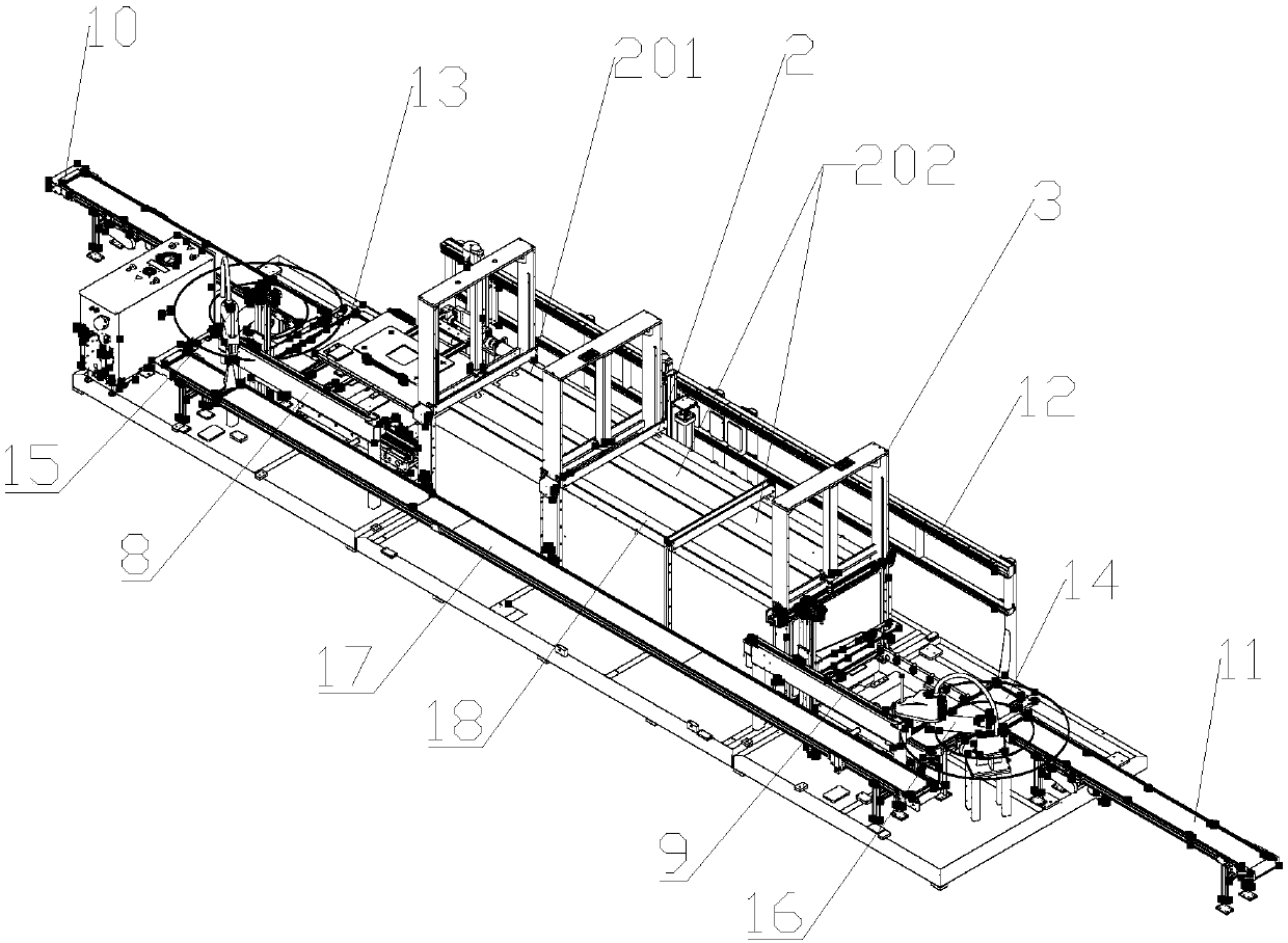
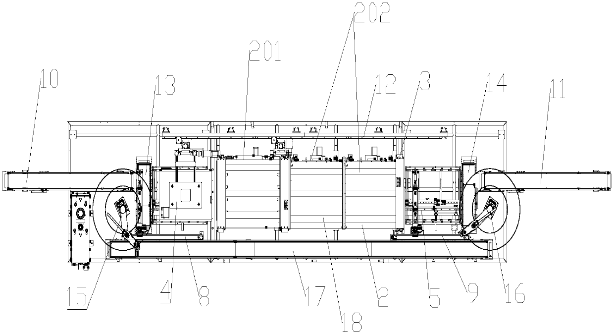
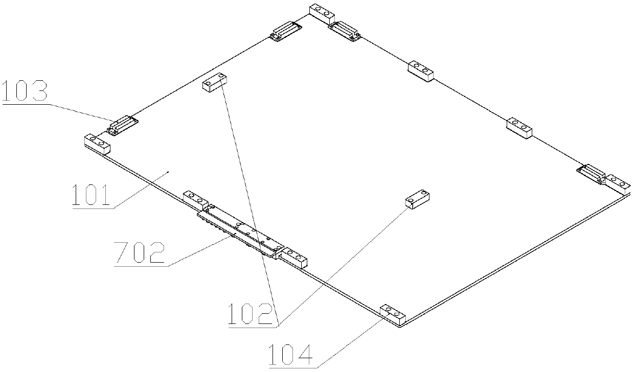
[0027] A tunnel vacuum furnace based on a single-plate reflow type, comprising several laminates 1 and several tunnel cavities 2, the tunnel cavities 2 are in contact with the outside through an atmospheric pressure plate valve 3, and the two sides of the tunnel cavity 2 are provided with There are an upper material level 4 and a lower material level 5, the upper material level 4, the lower material level 5 and the bottom of the tunnel cavity 2 are equipped with a laminate transmission and p...


PUM


Abstract

The invention discloses a tunnel vacuum furnace based on veneer backflow. The tunnel vacuum furnace comprises a plurality of laminates and a plurality of tunnel cavities. The tunnel cavities make contact with the outside world through ordinary pressure plate valves. The two sides of the tunnel cavities are provided with a feed position and a discharge position. A laminate transmission and locatingmechanisms is installed at the bottoms of the feed position, the discharge position and the tunnel cavities. Laminate heating devices are arranged in the tunnel cavities and comprise movable contactsand stationary contacts. The movable contacts are installed on the side faces in the tunnel cavities and are connected with jacking mechanisms. The stationary contacts are installed on single-layer plates. The two ends of the tunnel cavities are provided with a feed mechanism and a discharge mechanism correspondingly. The other ends of the feed mechanism and the discharge mechanism are provided with a feed pull belt and a discharge pull belt correspondingly. The side edges of the tunnel cavities and the ordinary pressure plate valves are further provided with laminate backflow devices. According to the tunnel vacuum furnace, the overall occupation space of equipment is saved, overall cost of the equipment is lowered, and the risk of air leakage of an electricity box is eliminated.

Description

technical field [0001] The invention relates to the technical field of product drying, in particular to a tunnel vacuum furnace based on a single-plate reflow type. Background technique [0002] At present, there are mainly two kinds of equipment in the market, single furnace and tunnel furnace. The single-body furnace requires a separate drying room, which has high operation and maintenance costs, low production capacity, and a large floor space; the vacuum tunnel furnace has high efficiency and does not require a separate drying room, but it uses a trolley backflow method and occupies a small area. It is relatively large; at the same time, the electric box is controlled to move with the trolley, and the air from the outside of the cavity enters the electric box of the trolley inside the cavity for cooling, which is prone to air leakage; and the loading and unloading module is more complicated and the cost is high. On the basis of the tunnel furnace, the present invention ...

Claims


Application Information

Patent Timeline
Patent Type & Authority Applications(China)
IPC IPC(8): F26B15/16F26B5/04F26B23/04F26B25/00
CPCF26B15/16F26B5/041F26B23/04F26B25/003
Inventor 张孝平文青松汪毅李政阳尚允坤
Owner CHANGZHOU DACHENG VACUUM TECH CO LTD
Why Eureka
Try Eureka