
Conveying adjusting device for LED lamp machining and using method thereof

A technology for LED lights and control devices, applied in the control input, heating method, application and other directions involving users/components, can solve problems such as breakage, inability to ensure uniform and orderly displacement and feeding of LED lights, and sliding of LED lights, etc. Convenient operation, simple structure, avoid slipping and breaking effect

Active Publication Date: 2019-04-09
孔含之
View PDF4 Cites 7 Cited by
  • Summary
  • Abstract
  • Description
  • Claims
  • Application Information

AI Technical Summary

Problems solved by technology

[0003] LED lights need to be transported by conveyor belts during the processing process. The previous process of LED lights is shifted to the next process through the conveyor belt. During the shifting process, multiple LED lights often gather together to form accumulations, which cannot be achieved. Ensure that the LED lights are shifted and fed evenly and orderly, causing the LED lights to slip off the conveyor belt and cause damage. In view of this, we propose a transmission control device for LED light processing

Method used


Image

  • Conveying adjusting device for LED lamp machining and using method thereof
  • Conveying adjusting device for LED lamp machining and using method thereof
  • Conveying adjusting device for LED lamp machining and using method thereof

Examples


Embodiment Construction

[0024] The following will clearly and completely describe the technical solutions in the embodiments of the present invention with reference to the accompanying drawings in the embodiments of the present invention. Obviously, the described embodiments are only some, not all, embodiments of the present invention. Based on the embodiments of the present invention, all other embodiments obtained by persons of ordinary skill in the art without creative efforts fall within the protection scope of the present invention.

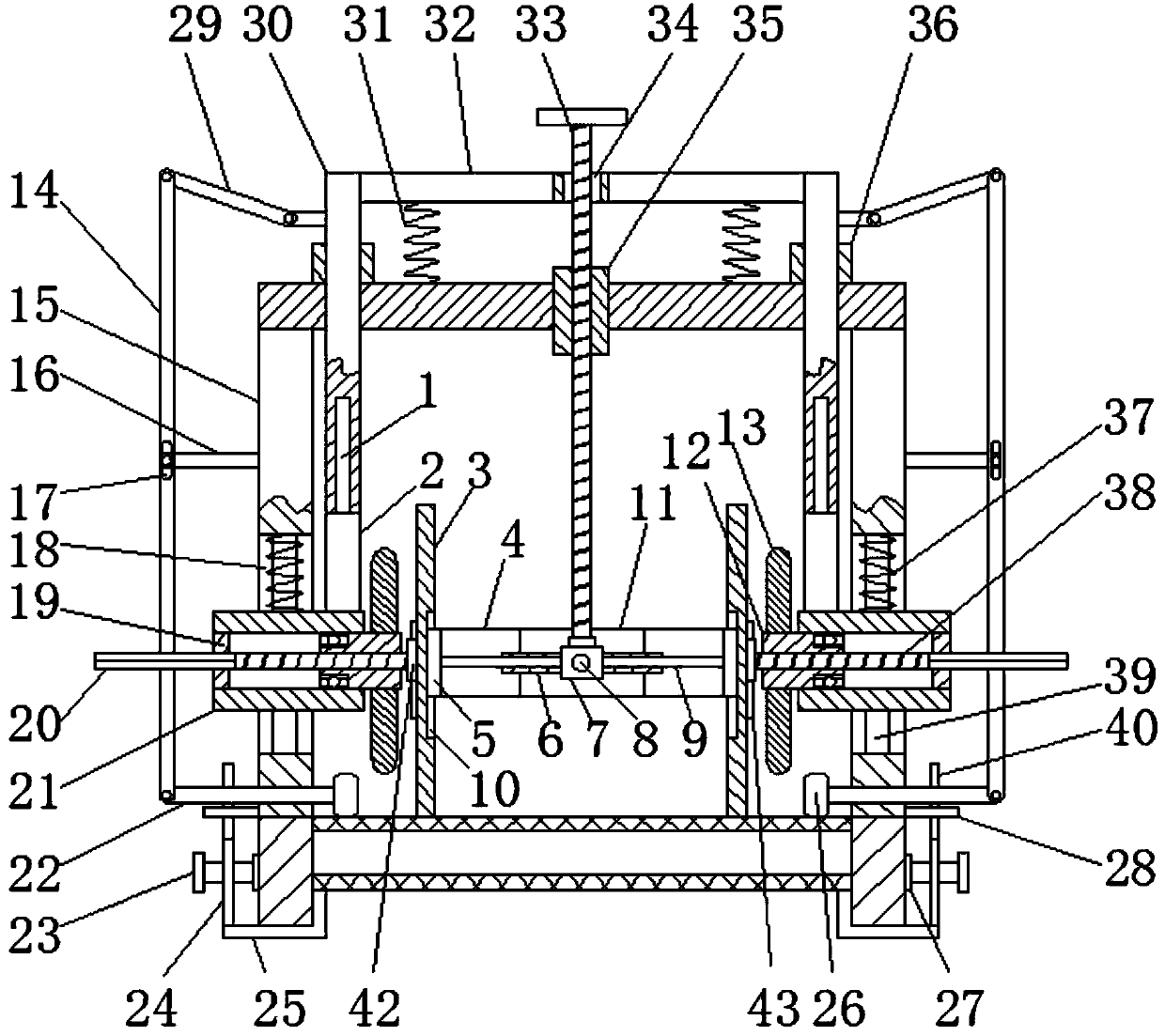
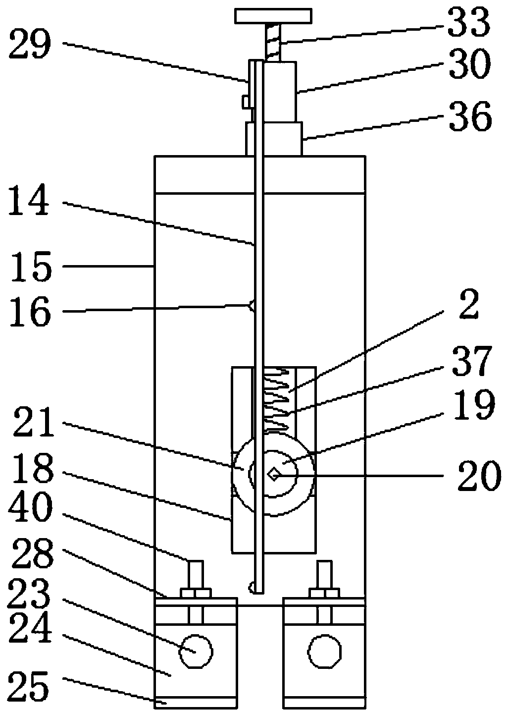
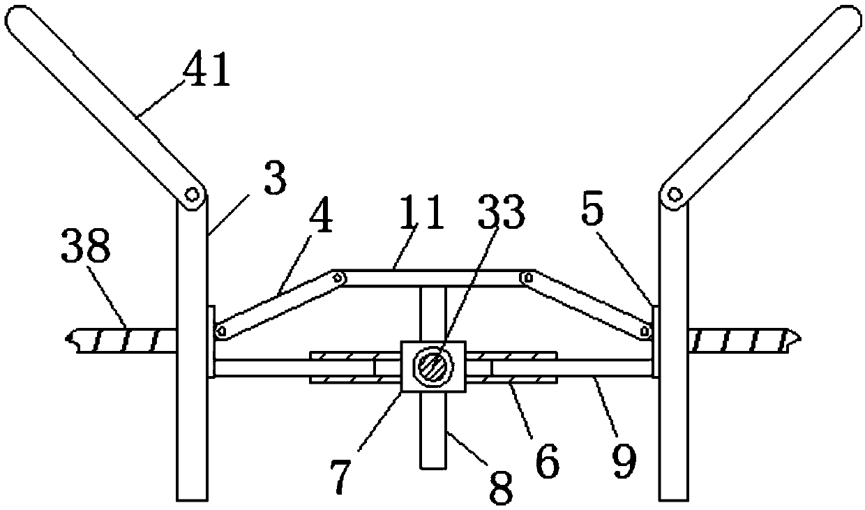
[0025] see Figure 1-4 , the present invention provides a technical solution: a transmission control device for LED lamp processing includes a gantry frame 15, the gantry frame 15 spans both sides of the conveyor belt, and the two lower ends of the gantry frame 15 are respectively fixedly connected by a clamping mechanism On the frame on both sides of the conveyor belt, the two vertical frames of the gantry frame 15 are provided with chute two 18, and the inside of...


PUM


Abstract

The invention relates to the field of lamp feeding, in particular to a conveying adjusting device for LED lamp machining and a using method thereof. The conveying adjusting device for LED lamp machining comprises a portal frame, the portal frame stretches across the two sides of a conveyer belt, and the two lower ends of the portal frame are fixedly connected to the portions, on the two sides of the conveyer belt, of a rack through clamping mechanisms separately; two vertical frames of the portal frame are each provided with a second sliding groove, an adjustable width limiting portion is connected to the interior of each second sliding groove, each width limiting portion comprises a sleeve slidably connected to the interior of the corresponding second sliding groove, a width limiting plate is connected to the interior of each sleeve through a width adjusting mechanism, and the two width limiting plates are located on the inner side of the portal frame and oppositely arranged; and eachwidth limiting portion further comprises a narrowness adjusting mechanism, and an adjustable height limiting mechanism is connected between the two width limiting plates. According to the conveying adjusting device for LED lamp machining, width and narrowness adjusting is conducted on the width limiting plates through the width adjusting mechanisms and the narrowness adjusting mechanism, height adjusting is conducted on a height limiting plate through the height limiting mechanism, operation is easy and convenient, the portal frame is assembled and disassembled through the clamping mechanisms, the structure is simple, and operation is convenient.

Description

technical field [0001] The invention relates to the field of lamp material feeding, in particular to a transmission control device for processing LED lamps and a use method thereof. Background technique [0002] The basic structure of the LED lamp is an electroluminescent semiconductor material chip, which is cured on the bracket with silver glue or white glue. The shock resistance of the LED lamp is good. The field of application involves mobile phones, table lamps, home appliances and other daily household appliances and machinery production. [0003] LED lights need to be transported by conveyor belts during the processing process. The previous process of LED lights is shifted to the next process through the conveyor belt. During the shifting process, multiple LED lights often gather together to form accumulations, which cannot be achieved. To ensure that the LED lamps are shifted and fed evenly and orderly, causing the LED lamps to slip off the conveyor belt and cause d...

Claims


Application Information

Patent Timeline
Patent Type & Authority Applications(China)
IPC IPC(8): B65G47/22
CPCB65G47/22F24F11/66F24F11/46F24F11/80F24F11/86F24F2120/14F24F2120/20F24F2140/60F24F2120/00
Inventor 孔含之
Owner 孔含之
Learn More