
Multifunctional space vector modulation method for current-source converter

A technology of space vector modulation and current source type, which is applied in the direction of converting AC power input to DC power output, electrical components, and high-efficiency power electronics conversion, and can solve unfavorable system insulation, high peak common-mode voltage of converters, grid nodes, etc. Leading power factor and other issues

Active Publication Date: 2019-04-05
TIANJIN UNIV
View PDF4 Cites 6 Cited by
  • Summary
  • Abstract
  • Description
  • Claims
  • Application Information

AI Technical Summary

Problems solved by technology

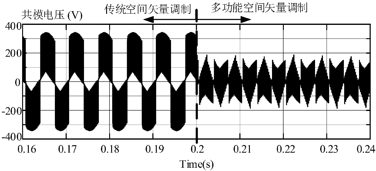
[0003] Since the traditional space vector modulation method does not select the zero vector, the peak value of the common mode voltage of the converter is high, which is not conducive to the insulation of the system
The method of adding common-mode reactors can reduce the influence of common-mode voltage to a certain extent, but it will increase the size and cost of the system
On the other hand, due to the existence of the filter capacitor of the LC filter circuit on the AC side of the converter, the power grid node will have a leading power factor

Method used


Image

  • Multifunctional space vector modulation method for current-source converter
  • Multifunctional space vector modulation method for current-source converter
  • Multifunctional space vector modulation method for current-source converter

Examples


Embodiment Construction

[0037] The specific implementation of the current source converter-based multifunctional space vector modulation method of the present invention will be described below in conjunction with the accompanying drawings, so that those skilled in the art can better understand the present invention.

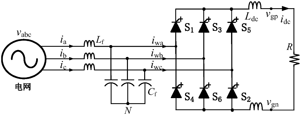
[0038] Taking the current source rectifier as an example, figure 1 It is a circuit diagram of a specific embodiment of the present invention. Such as figure 1 As shown, the current source rectifier uses a three-phase full-bridge topology as a rectifier circuit, and each full-bridge consists of six power switch tubes, which in this embodiment are IGBTs (Insulated Gate Bipolar Transistor, Insulated Gate Bipolar Transistor) with reverse diodes. type transistors).

[0039] The basic steps of the multifunctional space vector modulation method for the current source rectifier of the present invention are as follows:

[0040] Step 1: According to the constraints of the current source conver...


PUM


Abstract

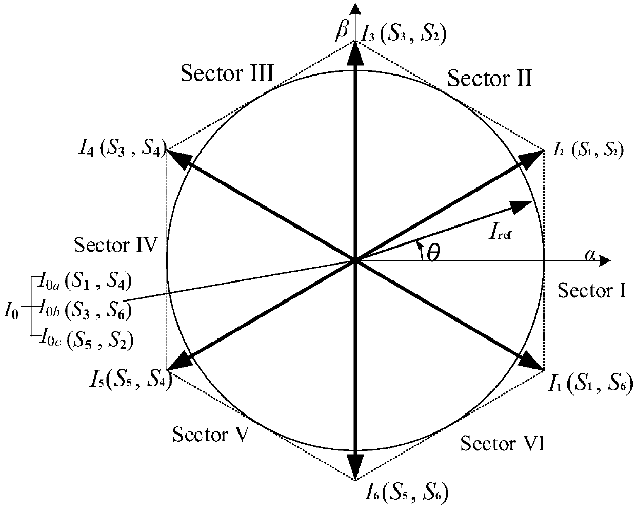
The invention discloses a multifunctional space vector modulation method for a current-source converter. The method can compensate the system reactive power while reducing the common-mode voltage of the current-source converter, and comprises steps of 1, mapping the nine switching current states of the current-source converter to nine vector states in an [alpha][beta] space coordinate system according to the clark transform; 2, calculating the common-mode voltage corresponding to each vector, and providing a method of selecting a zero vector to reduce the system common-mode voltage; 3, transforming the voltage and current of the grid-connected point of the converter into the dq coordinates, controlling the active power and the reactive power of the system by controlling the d-axis currentand the q-axis current of the converter respectively, and accordingly determining a converter modulation reference vector; and 4, determining the three switch vectors of a composite reference vector based on an ampere-second balance principle, and then determining a zero-vector corresponding switch state according to the method in step 2. The modulation method realizes active power and reactive power independent control through the dq coordinate transformation, and uses the zero vector with the lowest common-mode voltage for synthesizing the reference vector to reduce the common-mode voltage of the system.

Description

technical field [0001] The invention relates to a multifunctional current source converter space vector modulation method, in particular to a modulation method capable of simultaneously reducing the common mode voltage of the current source converter and realizing the maximum power factor operation of the converter. Background technique [0002] Converter technology is a technology that converts electrical energy from DC to AC or AC to DC, and plays an important role in today's industrial applications. Three-phase current source converters are widely used. The principle is to use switching tubes to build the main circuit, and then cooperate with the corresponding modulation method to control the switching state of the switching tubes, so that the input / output current waveform is approximately sinusoidal. The basic principle of the space vector modulation method of the current source converter is to convert the nine kinds of PWM current states of the current source type three...

Claims


Application Information

Patent Timeline
IPC IPC(8): H02M7/00H02M1/42
CPCH02M1/42H02M7/00H02M1/0038H02M1/123Y02B70/10
Inventor 何晋伟张昌浩李强
Owner TIANJIN UNIV
Learn More