
Distribution network regional voltage distributed coordinated control method and system

A distributed coordination and control method technology, applied in AC network voltage adjustment, photovoltaic power generation, electrical components, etc., can solve problems such as time-space mismatch between power supply and load, and voltage over-limit

Active Publication Date: 2019-04-05
TIANJIN UNIV +4
View PDF2 Cites 13 Cited by
  • Summary
  • Abstract
  • Description
  • Claims
  • Application Information

AI Technical Summary

Problems solved by technology

[0007] The purpose of the present invention is to provide a distribution network regional voltage distributed coordinated control method and system to solve the problem of time-space mismatch between power supply and load and voltage limit in the distribution network containing high-permeability photovoltaics

Method used


Image

  • Distribution network regional voltage distributed coordinated control method and system
  • Distribution network regional voltage distributed coordinated control method and system
  • Distribution network regional voltage distributed coordinated control method and system

Examples


Embodiment 1

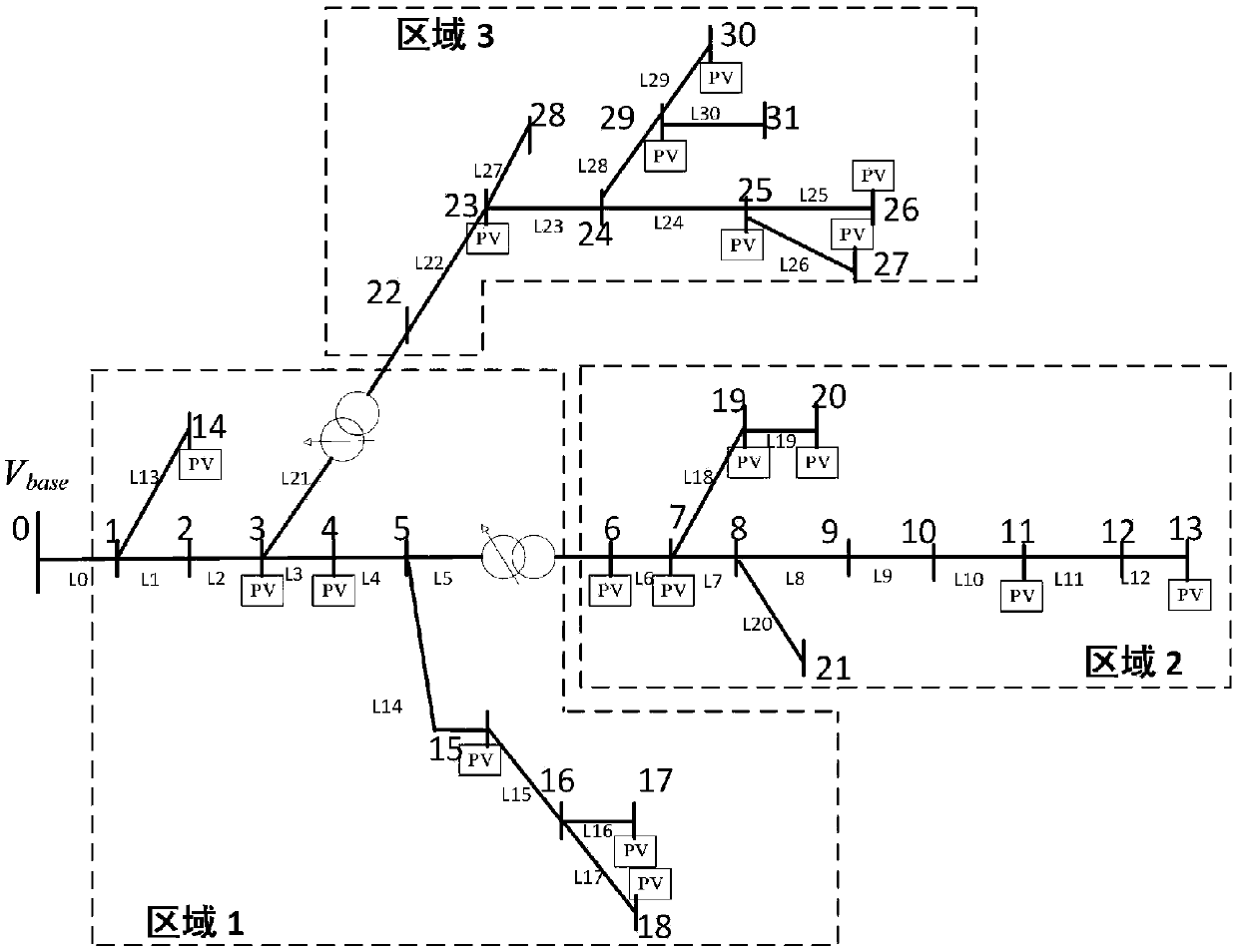
[0151] Embodiment 1: 32-node actual 10kV distribution network

[0152] Such as image 3 As shown, a 10kV line containing distributed photovoltaics with high penetration rate in a rural power grid in China is selected to verify the proposed regional voltage control strategy. The voltage of the head-end node is 1.0p.u., when it is running at full load without light, the voltage at node 6 is 0.9433p.u., the voltage at node 22 is 0.9503p.u., and the voltage loss rate is about 5%. Divided into three areas, the area division results are as follows image 3 shown.

[0153] Table 1 Parameters of controllable photovoltaic converter and reactive power compensation equipment

[0154]

[0155] The total photovoltaic installed capacity is about 2.22MVA, distributed in 18 nodes. Among them, the photovoltaic converter power of 12 nodes is controllable, and there are 4 nodes where reactive power compensation equipment is installed. The specific parameters are shown in Table 1. Althoug...

Embodiment 2

[0165] Embodiment 2: Improving IEEE123 node distribution network

[0166] In order to verify the applicability of the method of the present invention on a larger scale network, an improved IEEE123 node system is selected for analysis. The voltage of the head-end node is 1.0p.u., when there is no light and full load operation, the voltage at node 19 is 0.9467p.u., the voltage at node 68 is 0.8963p.u., and the voltage loss rate is about 5%. Divided into three areas, the area division results are as follows Figure 6 shown.

[0167] A overvoltage scenario

[0168] In a certain scenario, the voltage of the first node of the distribution station is 1.04p.u., and 12 distributed photovoltaics are close to full-capacity power generation. The installed capacity and location of photovoltaics are shown in Table 3 below.

[0169] Table 3 Installed capacity and location of distributed photovoltaics

[0170] install node

Installed capacity / MVA

13、108、115

0.6

...


PUM


Abstract

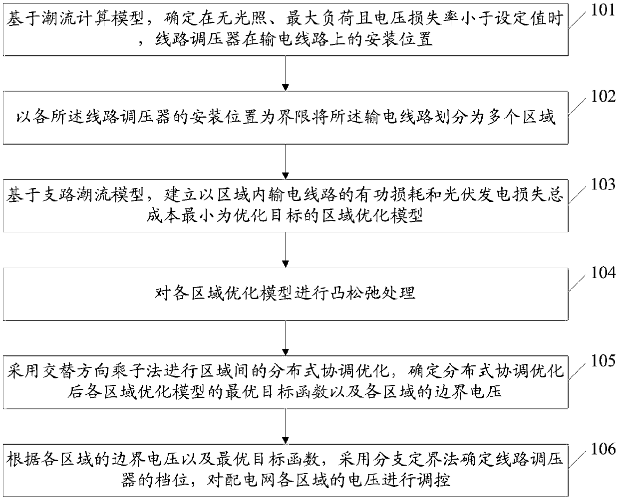
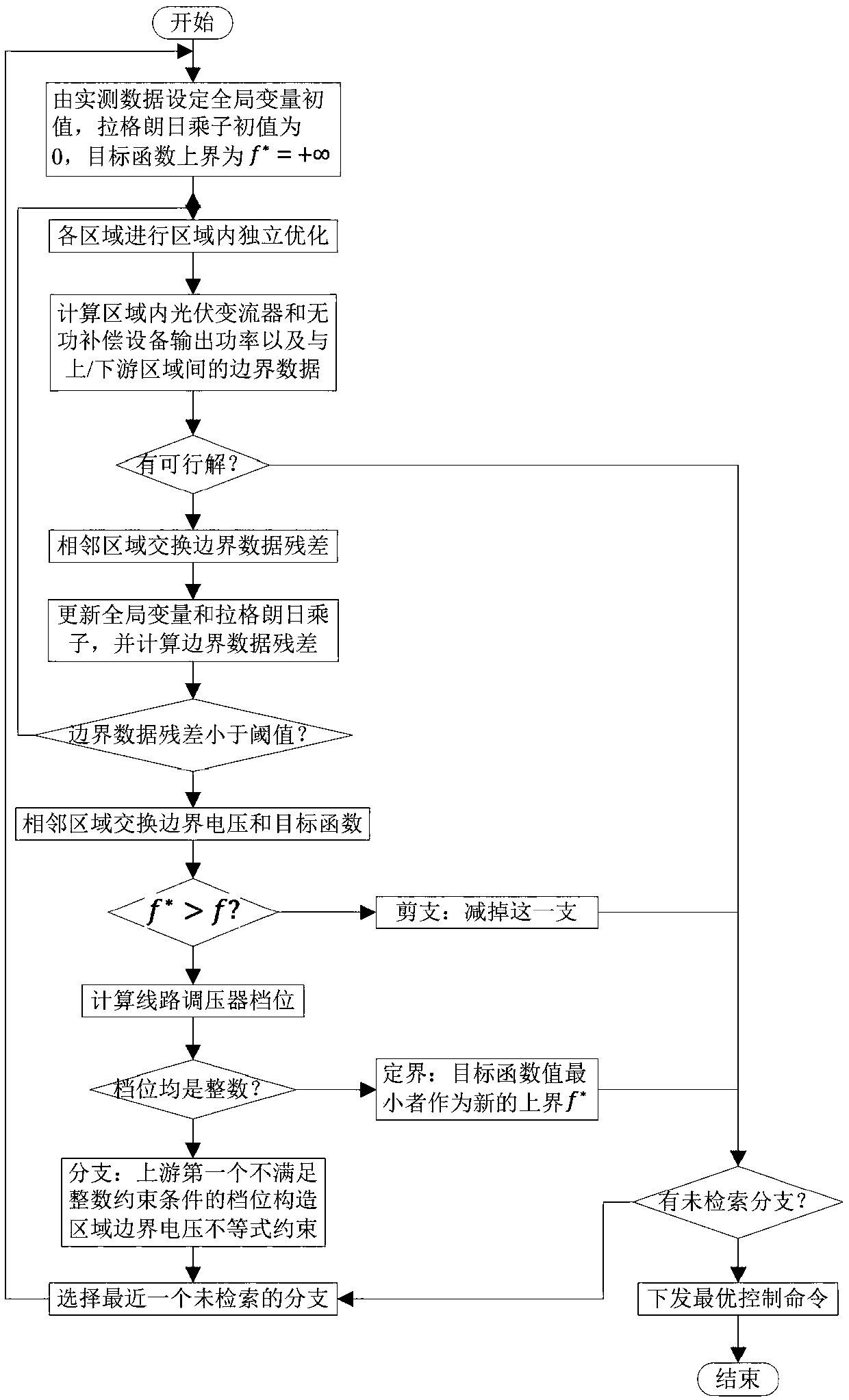
The invention discloses a distribution network regional voltage distributed coordinated control method and system. The method comprises a step of determining the installation positions of line voltageregulators in a power transmission line when there is no light, a load is maximum and a voltage loss rate is smaller than a set value, a step of dividing the power transmission line into multiple regions by using the installation positions of the line voltage regulators as boundaries, a step of establish a regional optimization model with the minimalization of the active loss of the power transmission line and the total cost of loss of photovoltaic power generation in the regions as an optimization target, a step of performing distributed coordination optimization between the regions by usingan alternating direction multiplier method and determining the optimal objective function of each regional optimization model and the boundary voltage of each region after distributed coordination optimization, and a step of determining the gear positions of the line voltage regulators by using a branch bound method, and regulating the voltage of each region of a distribution network. According to the invention, the problems of the time and space mismatch of a power supply with a high-permeability photovoltaic distribution network and the load and voltage out-of-limit can be solved.

Description

technical field [0001] The invention relates to the field of voltage regulation of a distribution network containing high-permeability photovoltaics, in particular to a method and system for distributed coordinated control of regional voltage of a distribution network. Background technique [0002] Aiming at the voltage regulation problem caused by high-permeability photovoltaics connected to the distribution network, the distributed coordinated control of the regional voltage of the distribution network is based on the precondition of qualified voltage, and the regional coordination optimization with the goal of minimizing the network loss and photovoltaic power generation loss cost. The existing technologies adopt centralized, decentralized and distributed optimization methods respectively, and the voltage regulation technologies for grid-connected distributed power sources will be described in detail below. [0003] As the power penetration rate of distributed photovoltai...

Claims


Application Information

Patent Timeline
IPC IPC(8): H02J3/12H02J3/38H02J3/00
CPCH02J3/008H02J3/12H02J3/383H02J2203/20Y02E10/56
Inventor 郭力路畅彭昱皓高爽柴园园王波虞殷树龚向阳王威贺旭冯烛明王晴张志雄应芳义石琦华建良曹松钱
Owner TIANJIN UNIV
Learn More