Absolute position coding and decoding method for optical grating of absolute position displacement sensor

A technology of displacement sensor and absolute position, which is applied in the direction of converting sensor output, instrument, measuring device, etc. It can solve the problems of limited installation space, increased encoder volume, and increased difficulty of circular grating manufacturing process, so as to reduce the amount of data, Prevents misreading of position signals and improves manufacturing accuracy

Active Publication Date: 2019-04-05
GUANGZHOU ACCUGLEN INTELLIGENT TECH LTD
View PDF9 Cites 7 Cited by
  • Summary
  • Abstract
  • Description
  • Claims
  • Application Information

AI Technical Summary

Problems solved by technology

The result is firstly that the manufacturing process of high-precision and high-resolution circular gratings is more difficult, and it also leads to an increase in the size of the encoder.
However, applications that require high precision and high resolution for encoders are often accompanied by strict restrictions on their installation space, which limits the high-precision performance of this type of circular grating that uses multi-turn Gray codes for absolute position coding and decoding. Application Promotion in Requested Application Areas
In addition, the increase in the code track width of this type of circular grating also requires corresponding adjustments in the shape of the photoelectric scanning sensor to ensure accurate reading of position data.

Method used


Image

  • Absolute position coding and decoding method for optical grating of absolute position displacement sensor
  • Absolute position coding and decoding method for optical grating of absolute position displacement sensor
  • Absolute position coding and decoding method for optical grating of absolute position displacement sensor

Examples


Embodiment 1

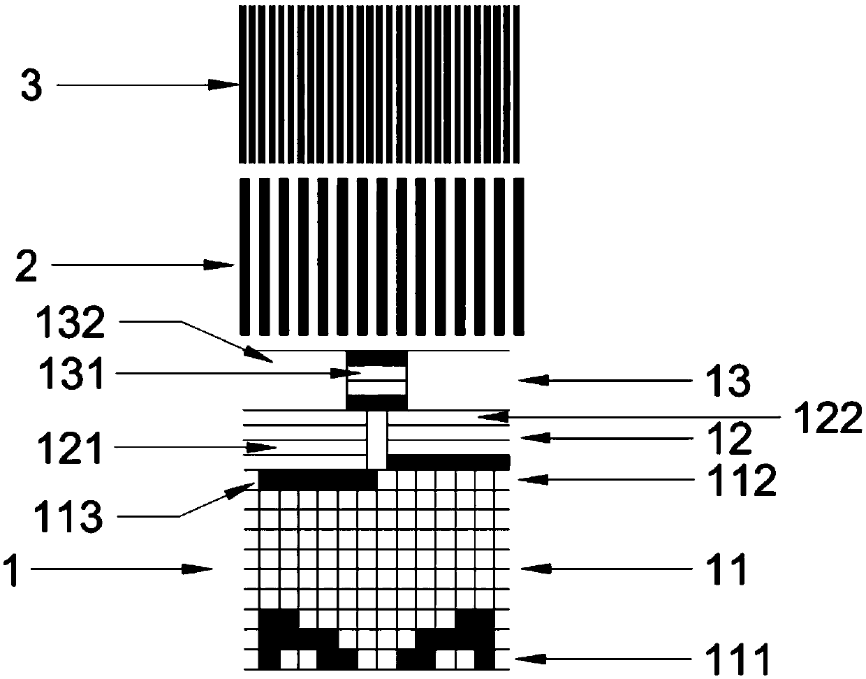
[0040] Such as figure 1 As shown, this embodiment is an absolute position displacement sensor grating absolute position encoding and decoding method, the linear grating absolute position encoding is divided into 3 code tracks, the first is absolute code track 1, the second code track, and the third code track is an equidistant incremental code track. The absolute code track 1 is composed of a Gray code area 11 , an interval code area 12 and an inter-interval code area 13 . The second code track is the low-order equidistant incremental code track 2, the number of reticle lines in the low-order equidistant incremental code track 2 is equal to the number of Gray codes, and the width of each low-bit equidistant incremental code track 2 is equal to half the width of the Gray code. That is, each Gray code corresponds to a complete low-bit equidistant incremental code track 2 reticle cycle unit. The third code track is the high equidistant incremental code track 3, and the number o...

Embodiment 2

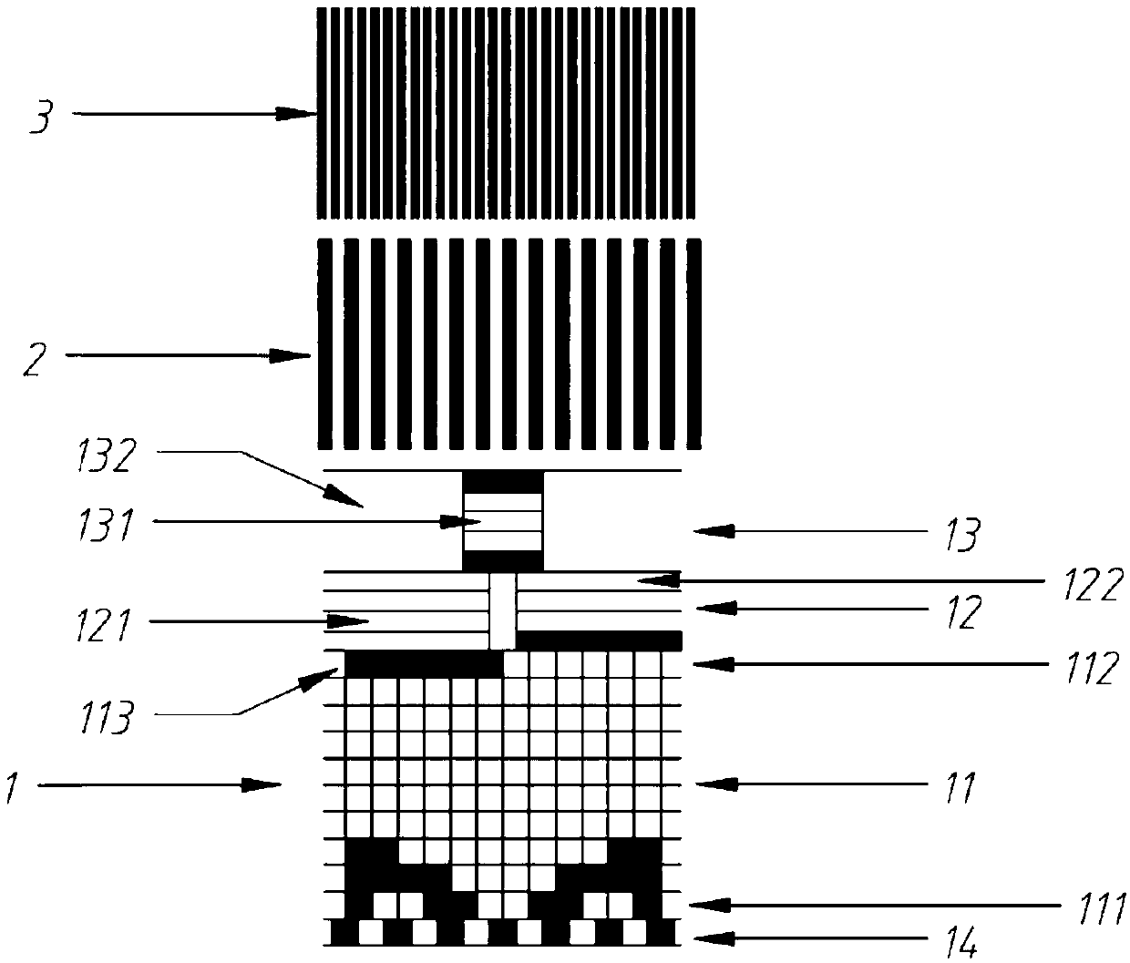
[0053] Such as image 3 As shown, in an absolute position displacement sensor grating absolute position encoding and decoding method in this embodiment, the absolute position encoding of the circular grating with a smaller diameter is divided into 3 code tracks, the first is absolute code track 1, and the second code track , The third code track is an equidistant incremental code track. The absolute code track 1 is composed of a gray code area 11 and a parity span identification code area 14 . The second code track is the low-bit equidistant incremental code track 2, the number of reticle lines in the low-bit equidistant incremental code track 2 is equal to the number of Gray codes, and the width of each low-bit equidistant incremental code track 2 is equal to half the width of a Gray code , that is, each Gray code corresponds to a complete low-bit equidistant incremental code track 2 reticle cycle unit. The third code track is the high equidistant incremental code track 3, ...

Embodiment 3

[0065] Such as figure 2 As shown, this embodiment is an absolute position displacement sensor grating absolute position encoding and decoding method, the linear grating absolute position encoding is divided into 3 code tracks, the first is absolute code track 1, the second code track, and the third code track is an equidistant incremental code track. The absolute code track 1 is composed of a parity span identification code area 14 , a Gray code area 11 , an interval code area 12 and a pass interval code area 13 . The second code track is the low-order equidistant incremental code track 2, the number of reticle lines in the low-order equidistant incremental code track 2 is equal to the number of Gray codes, and the width of each low-bit equidistant incremental code track 2 is equal to half the width of the Gray code. That is, each Gray code corresponds to a complete low-bit equidistant incremental code track 2 reticle cycle unit. The third code track is the high equidistant...


PUM


Abstract

The invention discloses an absolute position coding and decoding method for an optical grating of an absolute position displacement sensor. The absolute position coding and decoding method comprises the following steps that the optical grating with absolute position coding is divided into N code channels, wherein the first code channel is an absolute code channel, and the other n-1 code channels are equidistant increment code channels; the absolute code channel is composed of a parity bit cross-region identification code area, a gray code area, an interval code area (with or without) and an over-interval code area (with or without); the equidistant increment code channels comprise low-order equidistant increment code channels and high-order equidistant increment code channels which areprovided with evenly spaced scribing lines; the number of the scribing lines of the low-order equidistant incremental code channels is equal to the number of gray codes; the number of the scribing lines of the high-order equidistant incremental code channels can be arranged as required; the corresponding code is "1" when light passes through or reflects from an optical grating absolute code channel coding area to a photoelectric element, and the corresponding code is "0" is when light does not pass through or reflect to the photoelectric element; and during decoding, position data read by thecode channels are integrated through FPGA chips. The absolute position coding and decoding method can ensure that the absolute position coding within any coding length range is unique.

Description

technical field [0001] The invention belongs to the technical field of absolute position displacement sensors, in particular to a grating absolute position encoding and decoding method of an absolute position displacement sensor. Background technique [0002] The full-closed-loop direct position control scheme is the mainstream high-precision control scheme in applications such as high-precision robots and high-end CNC machine tools. Among them, the position displacement sensor is the key sensor in the high-precision full-closed-loop direct position control scheme. The position displacement sensor using the absolute position encoding grating can directly feed back the current absolute position information when it is powered on, and does not need to go back to zero to find the absolute reference point to confirm the absolute position. Therefore, this type of absolute position displacement sensor has a wider range of applications. [0003] At present, the commonly used absol...

Claims


Application Information

Patent Timeline
Patent Type & Authority Applications(China)
IPC IPC(8): G01B11/02G01D5/347
CPCG01B11/02G01D5/347
Inventor 艾鹰董俊阎素珍
Owner GUANGZHOU ACCUGLEN INTELLIGENT TECH LTD
Why Eureka
Try Eureka