Bearing capacity experiment device for foundation for civil engineering
A technology of foundation bearing capacity and experimental equipment, which is applied in the field of foundation experiments, can solve problems such as boring, boring, and unfavorable learning in the classroom teaching process
- Summary
- Abstract
- Description
- Claims
- Application Information
AI Technical Summary
Problems solved by technology
Method used
Image
Examples
Embodiment 1
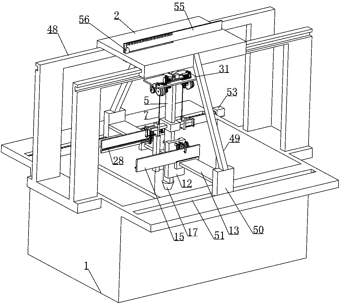
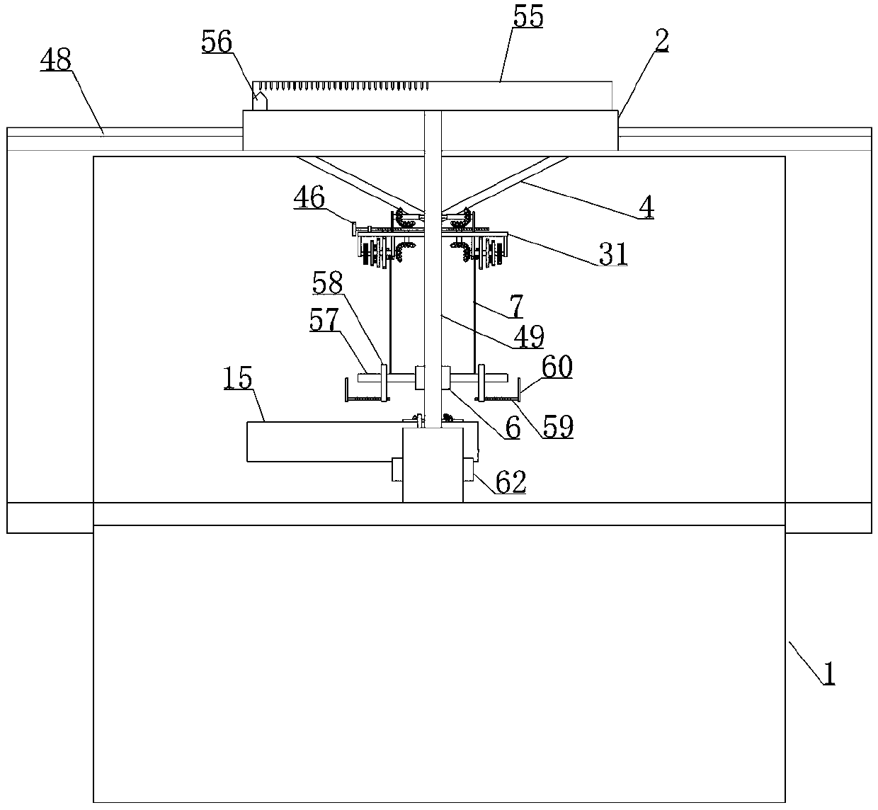
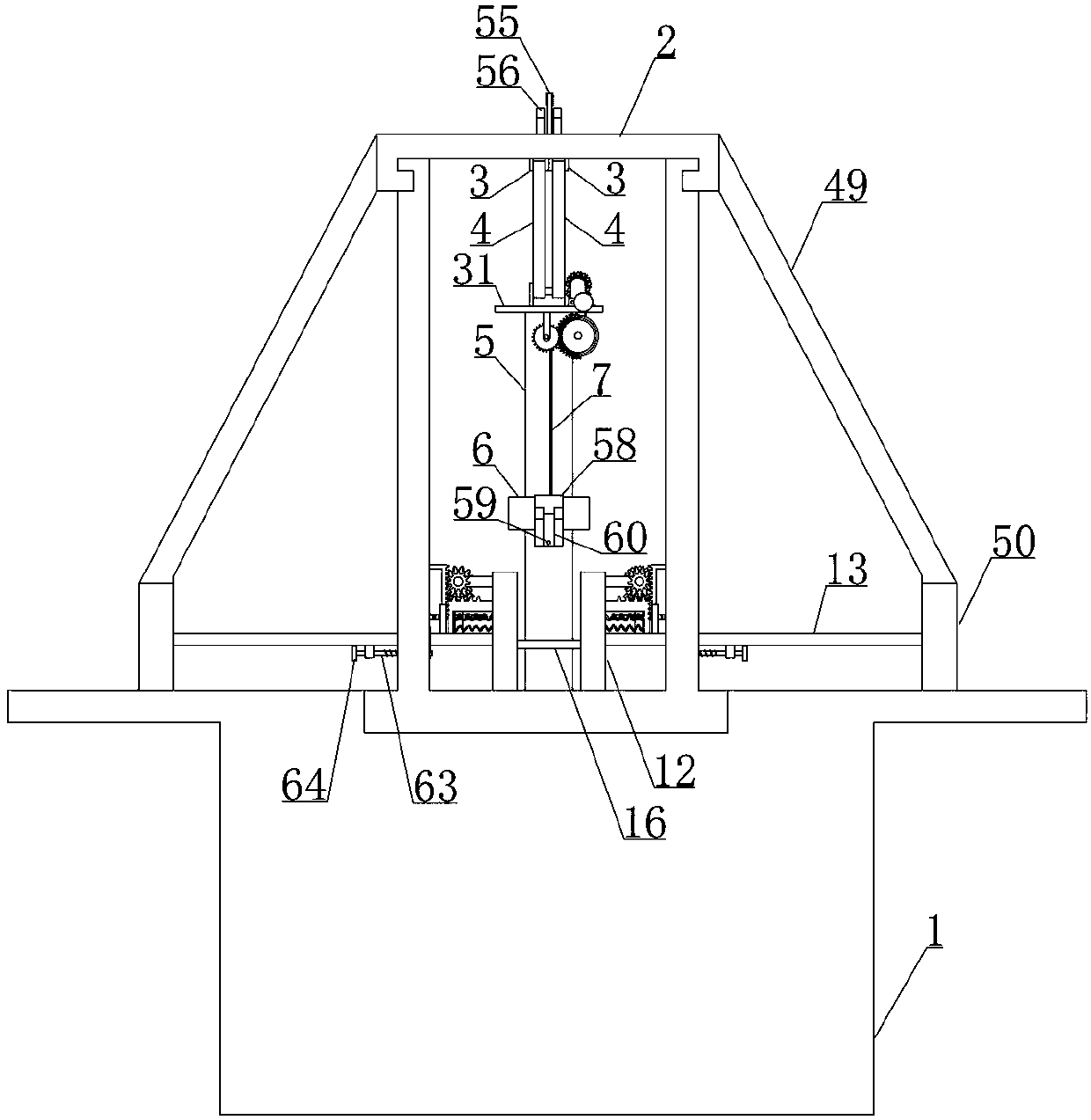
[0036] Embodiment 1, a ground bearing capacity test device for civil engineering, including an experimental box 1, is characterized in that a top plate 2 is fixed at intervals above the experimental box 1 and two sliders 3 are horizontally slidably connected to the lower end surface of the top plate 2 The lower end surface of the slider 3 is rotatably connected to the connecting rod 4 and the other end of the connecting rod 4 is rotatably connected to the vertically arranged rectangular rod 5. The rectangular rod 5 is provided with a rectangular hammer 6 slidingly matched with it. The warp wire 7 is driven by a wire wheel 8 that is rotatably connected to the top of the rectangular rod 5 . The wire wheel 8 is rotatably connected to the first gear 9 and the first gear 9 is engaged with the first half that is rotatably connected to the top of the rectangular rod 5 . Gear 10, the first half gear 10 is driven by the bevel gear set arranged on the top of the rectangular rod 5 and the...
Embodiment 2
[0041] Embodiment 2, on the basis of Embodiment 1, the trigger mechanism is a trigger rod 18 that is longitudinally slidably connected to the guide rail 12 and the trigger rod 18 is placed on one side of the guide rail 12, and the upper and lower ends are inclined. The marking device includes: The trigger lever 18 is placed on the outer side of the guide rail 12 and is fixedly connected with a first rack 19, and the first rack 19 is longitudinally slidably connected to the support plate 13. The gear 20 and the drive gear 20 lateral sides are respectively provided with a first marking bevel gear 21 and a marking gear 22 which rotate coaxially with it. The upper end of the rack 23 and the second rack 23 is fixed with an L-shaped bar 24, and the vertical part of the L-shaped bar 24 is fixed with a marking pen 25 that cooperates with the recording board 15. The second marking bevel gear 26 on the supporting plate 13 and the second marking bevel gear 26 coaxially rotate with a one-...
Embodiment 3
[0043] Embodiment 3, on the basis of Embodiment 2, the reset mechanism includes: the end of the first rack 19 away from the guide rail 12 is fixedly connected with a vertically arranged sliding rod 29 and the sliding rod 29 is longitudinally slidably connected to the supporting plate 13, Return springs 30 are fixed vertically at intervals on one side of the sliding rod 29 facing the guide rail 12 , and the other end of the return spring 30 is fixed on the side wall of the guide rail 12 .
[0044] When this embodiment is in use, we set a resetting mechanism for resetting the trigger lever 18 on the scribing device, so that when the rectangular hammer 6 passes over the trigger lever 18, the trigger lever 18 will be restored to its original state. Specifically, the first One end of a rack 19 away from the guide rail 12 is fixedly connected with a vertically arranged sliding rod 29 and the sliding rod 29 is longitudinally slidably connected to the support plate 13, and the side of ...
PUM
 Abstract
Description
Claims
Application Information
 - Generate Ideas
- Intellectual Property
- Life Sciences
- Materials
- Tech Scout
- Unparalleled Data Quality
- Higher Quality Content
- 60% Fewer Hallucinations
Browse by: Latest US Patents, China's latest patents, Technical Efficacy Thesaurus, Application Domain, Technology Topic, Popular Technical Reports.
© 2025 PatSnap. All rights reserved.Legal|Privacy policy|Modern Slavery Act Transparency Statement|Sitemap|About US| Contact US: help@patsnap.com


