Damping bearing for a bridge
A technology for bridges and damping, applied in the direction of bridges, bridge construction, bridge parts, etc., can solve the problems of capacity failure, low horizontal load energy dissipation capacity, damping bearing damage, etc., to achieve strong energy dissipation capacity, high performance, and improved Effectiveness
- Summary
- Abstract
- Description
- Claims
- Application Information
AI Technical Summary
Problems solved by technology
Method used
Image

Examples
specific Embodiment approach 1
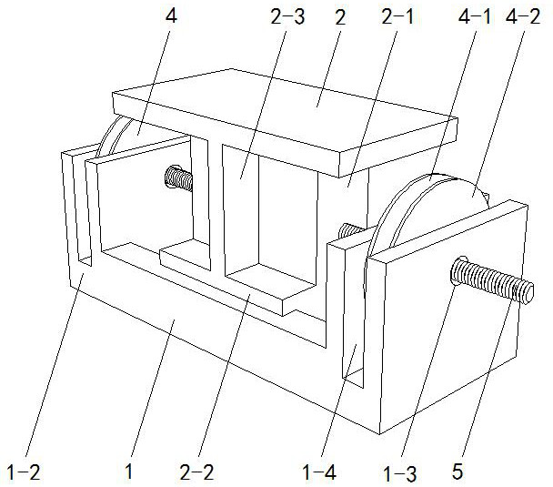
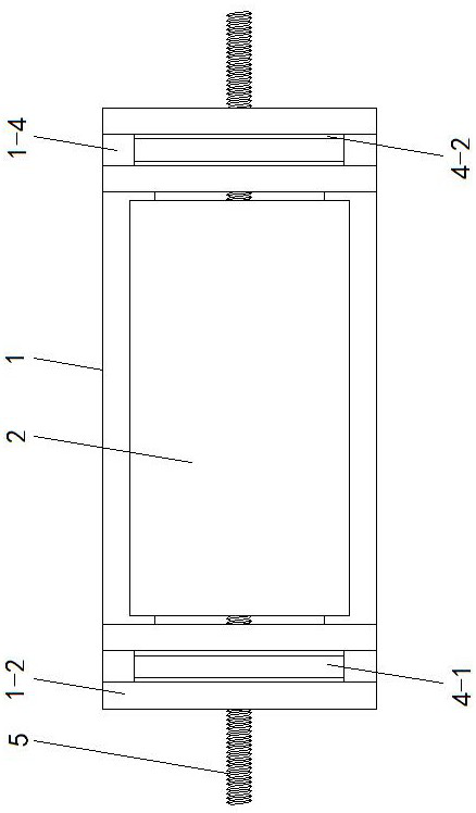
[0016] Specific implementation mode one: as Figure 1~Figure 8 As shown, the present invention discloses a bridge damping bearing, comprising a base 1, a top plate 2 and two damping devices, the upper surface of the base 1 is provided with a chute 1-1 along the length direction, and the chute 1 Both ends of -1 are vertically provided with baffles 1-2, the base 1 and the two baffles 1-2 are U-shaped and integrated, and the middle positions of the two baffles 1-2 are respectively provided with Perforation 1-3, installation grooves 1-4 are recessed in the middle of the upper end surfaces of the two baffles 1-2 along the width direction, the top plate 2 is horizontally arranged above the base 1, and the bottom of the top plate 2 is integrally connected by the vertical plate 2-1 There is a slider 2-2, and the slider 2-2 is slidably connected to the middle section of the chute 1-1, the chute 1-1 is preferably an inverted T-shaped structure, and the slider 2-2 is matched with the chu...
specific Embodiment approach 2
[0017] Specific implementation mode two: as Image 6 , 7 , 8, this embodiment is a further description of specific embodiment 1, the two ends of the sun gear 3-1 are respectively provided with a gap between the inner surface of the corresponding circular plate 4-2, and the two sides of the sun gear 3-1 The end faces are respectively coaxially recessed with an annular groove 1 3-6, and the inner surface of the circular plate 4-2 is coaxially recessed with an annular groove 2 4-4, the annular groove 1 3-6 and the annular groove 2 4-4 Oppositely fit with a group of balls 7 sandwiched between them.
specific Embodiment approach 3
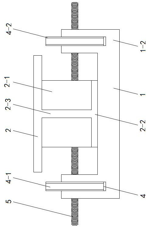
[0018] Specific implementation mode three: as figure 2 , 5 As shown, this embodiment is a further description of the specific embodiment 1. The length of each screw lever 5 is sufficient. When the top plate 2 slides to the two ends of the base 1 along the chute 1-1, The two wire levers 5 are not disengaged from the corresponding sun gear 3-1.
[0019] The present invention is installed between the beam body and the bridge pier when in use, the base 1 is fixed to the upper surface of the bridge pier, and the top plate 2 is fixed to the lower surface of the beam body. Generally, it is arranged vertically according to the bridge. The principle is: when the beam body is subjected to horizontal When the load generates the longitudinal displacement of the bridge, the top plate 2 fixed to the beam body moves relative to the base 1 along the chute 1-1, and the two screw levers 5 cooperate with the two planetary gear mechanisms 3 to convert the linear motion into rotation movement, ...
PUM
 Abstract
Description
Claims
Application Information
 - Generate Ideas
- Intellectual Property
- Life Sciences
- Materials
- Tech Scout
- Unparalleled Data Quality
- Higher Quality Content
- 60% Fewer Hallucinations
Browse by: Latest US Patents, China's latest patents, Technical Efficacy Thesaurus, Application Domain, Technology Topic, Popular Technical Reports.
© 2025 PatSnap. All rights reserved.Legal|Privacy policy|Modern Slavery Act Transparency Statement|Sitemap|About US| Contact US: help@patsnap.com