
A bridge non-contact deformation measurement method based on feature point tracking

A non-contact, measurement method technology, applied in image data processing, instruments, calculations, etc., can solve the problems of cumbersome layout and acquisition system, and achieve the effect of abundant SURF detection, fast calculation speed and high precision

Active Publication Date: 2019-04-02
SOUTHEAST UNIV
View PDF4 Cites 10 Cited by
  • Summary
  • Abstract
  • Description
  • Claims
  • Application Information

AI Technical Summary

Problems solved by technology

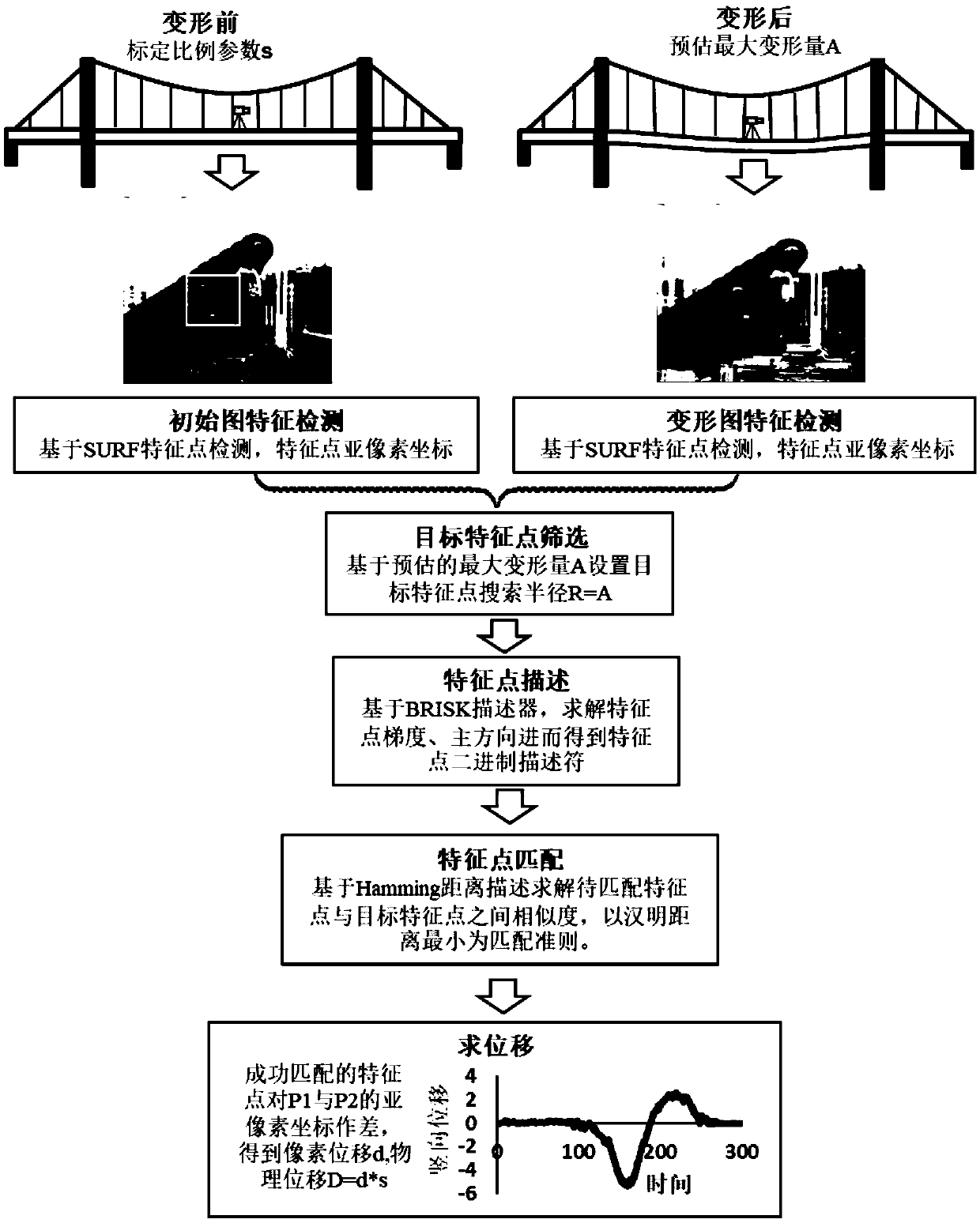
[0007] In order to overcome the shortcomings and deficiencies in the current technology, the purpose of the present invention is to provide a bridge non-contact deformation measurement method based on feature point tracking. The present invention overcomes the cumbersome defects of traditional contact bridge deflection measurement equipment arrangement and acquisition system, Compared with existing optical measurement methods, it does not need to paste characteristic targets on the structure but directly utilizes structural features, truly realizing non-contact

Method used


Image

  • A bridge non-contact deformation measurement method based on feature point tracking
  • A bridge non-contact deformation measurement method based on feature point tracking
  • A bridge non-contact deformation measurement method based on feature point tracking

Examples


Embodiment 1

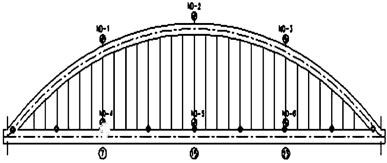
[0037] In the following, a typical bridge load test case is used to illustrate the implementation steps of the proposed rapid bridge deformation measurement method based on feature point tracking. First of all, let me introduce the static load test conditions measured by optical measurement on the same day. Six trucks with a single vehicle weight of 34 tons are used for loading. After the bridge deck is empty, the trucks are ready at the bridge head and stop at each eighth test point, such as image 3 As shown in , this optical measurement needs to monitor the deflection near the green measuring point. Each octant measuring point should stop for at least 10 minutes to ensure that the structure is completely deformed. The traditional measuring equipment used to measure the deformation of each octant measuring point on that day includes a level and an inclinometer. The following are the implementation steps when photometry is involved:

[0038] Step 1: Determine the layout of ...


PUM


Abstract

The invention discloses a bridge non-contact deformation measurement method based on feature point tracking. According to the method, a camera erected on a bridge measuring point is focused on a fixedstructure with negligible far deformation, a series of images of the fixed structure are collected before and after bridge loading, and an improved feature point matching algorithm SURF-BRISK is utilized for tracking the sub-pixel coordinates of the feature points in the image so as to obtain the sub-pixel displacement at the bridge measuring point, and then the pixel displacement is converted into the actual physical displacement through the calibrated scaling coefficient. According to the method, the complex process of installation during contact of traditional displacement measurement means such as a displacement meter inclinometer and the like is overcome, the defect that a pre-designed special target surface needs to be pasted on the surface of a structure in a traditional image measurement method is also overcome, an existing screening strategy for feature point matching is improved, and the matching accuracy and the working efficiency are improved. The method has the characteristics of non-contact, few preparation processes and convenience in measuring point positioning, and has a wide application prospect.

Description

technical field [0001] The invention belongs to the technical field of structural health monitoring, and in particular relates to a non-contact deformation measurement method for bridges based on feature point tracking. Background technique [0002] Displacement is one of the most critical basic parameters in bridge structure design and performance evaluation. It can directly reflect the basic performance and state of the structure. Therefore, the displacement of bridge structures has always been the focus of engineers and researchers. Existing displacement measurement equipment is mainly divided into two types: contact type and non-contact type. Contact displacement measurement equipment includes displacement meter inclinometer, level gauge, long gauge strain sensor, etc. However, there are various problems in the existing contact measurement equipment, and it is not fast and convenient enough in practical engineering applications. For example: the displacement meter needs...

Claims


Application Information

Patent Timeline
Patent Type & Authority Applications(China)
IPC IPC(8): G06T7/73G06T7/33
CPCG06T7/33G06T7/73
Inventor 张建于姗姗朱程鹏
Owner SOUTHEAST UNIV
Learn More